반응형
아침에 기상할 때 사용자의 생체 신호와 전 날 일사량 등을 판단해 가장 필요한 조명으로 사용자를 깨워주는 모닝 조명 알람 장치 개발. 제품 참고 링크
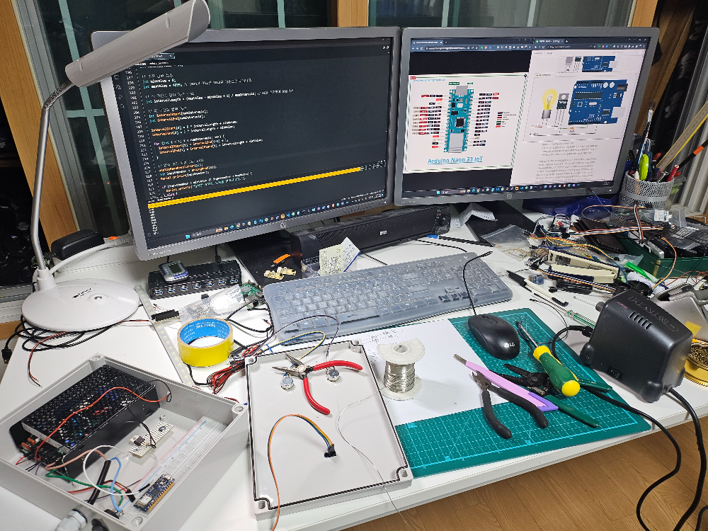
아래는 코드 전체. 사진은 서비스~
동작 시니리오!
1. 전원 on
- 빠르게 깜빡깜빡 두 번
2. 인터넷 연결 OK
- 시간 세팅 5분 단위 세팅 가능
- 정해진 시간 스마트 LED 동작 - 1분 17초 밝아짐. 가장 밝게 사용자가 끄기 전까지 지속
3. 인터넷 연결 안되면
- 30초간 인터넷 연결 시도하다가 안되면 1분간 off 상태 유지
- Smart LED 동작 - 1분 17초간 밝아짐. 가장 밝게 사용자가 끄기 전까지 지속
그리고 조명 밝기가 MAX된 후 15분간 ON된 후 Off 반드시하고
30초 후에 스마트조명 알람 진행이 반복되도록 해 주세요.
//#define SECRET_SSID "SK_Wㅠㅎ65464류흏iFiGIGAA988"
//#define SECRET_PASS "1806ㅠㅊ픂ㅊ74657456026356"

//#define SECRET_SSID "CAR6456E6B6546545G" // 5G can't connect.
//#define SECRET_PASS "8298"

#define SECRET_SSID "CARB"
#define SECRET_PASS "82998"
//intentionally error
//#define SECRET_PASS "8298"
/*
server address: http://api.sleep-doc.com/sleepq2/578f38a45732416d3ceb7899/2023/09/05
https://fishpoint.tistory.com/5156
*/


#include <SPI.h>
#include <WiFiNINA.h>
#include <WiFiUdp.h>

#include "arduino_secrets.h"

#include <Wire.h>
#include <Adafruit_GFX.h>
#include <Adafruit_SSD1306.h>

#define SCREEN_WIDTH 128 // OLED display width, in pixels
#define SCREEN_HEIGHT 64 // OLED display height, in pixels

#define OLED_RESET  4    // define display reset pin
Adafruit_SSD1306 display(OLED_RESET);

///////please enter your sensitive data in the Secret tab/arduino_secrets.h
char ssid[] = SECRET_SSID;        // your network SSID (name)
char pass[] = SECRET_PASS;    // your network password (use for WPA, or use as key for WEP)
int keyIndex = 0;            // your network key index number (needed only for WEP)

int status = WL_IDLE_STATUS;
// if you don't want to use DNS (and reduce your sketch size)
// use the numeric IP instead of the name for the server:
//IPAddress server(74,125,232,128);  // numeric IP for Google (no DNS)
char server[] = "api.sleep-doc.com";    // name address for Google (using DNS)

// Initialize the Ethernet client library
// with the IP address and port of the server
// that you want to connect to (port 80 is default for HTTP):
WiFiClient client;

const int light_pwm_pin = 5;

//time variable
//define timer sampling rate 1000=1sec
uint32_t sampleRate = 1000; //sample rate in milliseconds, determines how often TC5_Handler is called

uint32_t time_tick_onesecond=0;
uint32_t flag_10seconds = 0; //every 10second
uint32_t flag_300seconds = 0;

/*ntp variable*/
unsigned int localPort = 2390;      // local port to listen for UDP packets

//IPAddress timeServer(129, 6, 15, 28); // time.nist.gov NTP server -> time-a-g.nist.gov
IPAddress timeServer(132, 163, 96, 1); // time-a-b.nist.gov NTP server

const int NTP_PACKET_SIZE = 48; // NTP timestamp is in the first 48 bytes of the message

byte packetBuffer[ NTP_PACKET_SIZE]; //buffer to hold incoming and outgoing packets

// A UDP instance to let us send and receive packets over UDP
WiFiUDP Udp;
/*end*/

int global_utc_hour = 0; //global var for utctime hour
int global_utc_minute = 0; ////global var for utctime minute
int wifi_trycount = 0;
int flag_wifi_notconnect = 0;

void setup() {

  //Initialize serial and wait for port to open:
  Serial.begin(9600);
  initial_oled();
  pinMode(light_pwm_pin, OUTPUT);
  start_ledblink();

  //setup Timer
  tcConfigure(sampleRate); //configure the timer to run at <sampleRate>Hertz
  tcStartCounter(); //starts the timer

  String fv = WiFi.firmwareVersion();
  if (fv < WIFI_FIRMWARE_LATEST_VERSION) {
    Serial.println("Please upgrade the firmware");
  }

  // attempt to connect to WiFi network:
  while (status != WL_CONNECTED) {
    Serial.print("Attempting to connect to SSID: ");
    Serial.println(ssid);
    // Connect to WPA/WPA2 network. Change this line if using open or WEP network:
    status = WiFi.begin(ssid, pass);

    // wait 10 seconds for connection:
    wifi_trycount++;
    delay(2000);
    if(wifi_trycount == 3)
    {
      flag_wifi_notconnect = 1;
      Serial.println("Not Connected to WiFi");
      break;
    }
  }

  Serial.println("Connected to WiFi");
  printWifiStatus();

  Serial.println("\nStarting connection to server...");
  Udp.begin(localPort);

  //delay(20000);
}

void loop() {

  //every 10 second execute - ok
  if(flag_10seconds > 10){
    ntpserver_gettime(); //get utc time
    flag_10seconds = 0;
  }

  int alarm_hour = getAlarm_hour();
  int alarm_minute = getAlarm_minute() * 5;

  Serial.print(alarm_hour);
  Serial.print(" : ");
  Serial.print(alarm_minute);
  Serial.print(" : ");
  Serial.print(global_utc_hour);
  Serial.print(" : ");
  Serial.println(global_utc_minute);

  //connect -> compare -> led fade in
  if((global_utc_hour == alarm_hour) && (global_utc_minute == alarm_minute))
  {
    for(int i=0; i < 255; i++){
      setLight(i);
      delay(300);
    }
    setLight(255);
    while(1);
  }

  /*
  if(flag_wifi_notconnect == 0)
  {

    for(int i=0; i < 255; i++){
      setLight(i);
      delay(300);
    }
    setLight(255);
    while(1); //wait infinitly
  }*/

  //not connect
  if(flag_wifi_notconnect == 1)
  {
    setLight(0);
    delay(60000);

    for(int i=0; i < 255; i++){
      setLight(i);
      delay(300);
    }
    setLight(255);
    while(1); //wait infinitly
  }
  Serial.println(alarm_hour);
  Serial.println(alarm_minute*5);

  //smartlight_process();

  delay(500);
}

void ntpserver_gettime()
{
  sendNTPpacket(timeServer); // send an NTP packet to a time server
  // wait to see if a reply is available
  delay(1000);
  if (Udp.parsePacket()) {
    Serial.println("packet received");
    // We've received a packet, read the data from it
    Udp.read(packetBuffer, NTP_PACKET_SIZE); // read the packet into the buffer

    //the timestamp starts at byte 40 of the received packet and is four bytes,
    // or two words, long. First, extract the two words:

    unsigned long highWord = word(packetBuffer[40], packetBuffer[41]);
    unsigned long lowWord = word(packetBuffer[42], packetBuffer[43]);
    // combine the four bytes (two words) into a long integer
    // this is NTP time (seconds since Jan 1 1900):
    unsigned long secsSince1900 = highWord << 16 | lowWord;
    Serial.print("Seconds since Jan 1 1900 = ");
    Serial.println(secsSince1900);

    // now convert NTP time into everyday time:
    Serial.print("Unix time = ");
    // Unix time starts on Jan 1 1970. In seconds, that's 2208988800:
    const unsigned long seventyYears = 2208988800UL;
    // subtract seventy years:
    unsigned long epoch = secsSince1900 - seventyYears;
    // print Unix time:
    Serial.println(epoch);


    // print the hour, minute and second:
    Serial.print("The UTC time is ");       // UTC is the time at Greenwich Meridian (GMT)
    Serial.print(((epoch  % 86400L) / 3600)+9); // print the hour (86400 equals secs per day)
    global_utc_hour = ((epoch  % 86400L) / 3600) + 9; ///// hour
    Serial.print(':');
    if (((epoch % 3600) / 60) < 10) {
      // In the first 10 minutes of each hour, we'll want a leading '0'
    }
    Serial.print((epoch  % 3600) / 60); // print the minute (3600 equals secs per minute)
    global_utc_minute = (epoch  % 3600) / 60; ///// minute
    Serial.print(':');
    if ((epoch % 60) < 10) {
      // In the first 10 seconds of each minute, we'll want a leading '0'
    }
    Serial.println(epoch % 60); // print the second
  }
  // wait ten seconds before asking for the time again
  //delay(10000);
}

// send an NTP request to the time server at the given address
unsigned long sendNTPpacket(IPAddress& address) {
  // set all bytes in the buffer to 0
  memset(packetBuffer, 0, NTP_PACKET_SIZE);
  // Initialize values needed to form NTP request
  // (see URL above for details on the packets)
  packetBuffer[0] = 0b11100011;   // LI, Version, Mode
  packetBuffer[1] = 0;     // Stratum, or type of clock
  packetBuffer[2] = 6;     // Polling Interval
  packetBuffer[3] = 0xEC;  // Peer Clock Precision
  // 8 bytes of zero for Root Delay & Root Dispersion
  packetBuffer[12]  = 49;
  packetBuffer[13]  = 0x4E;
  packetBuffer[14]  = 49;
  packetBuffer[15]  = 52;

  // all NTP fields have been given values, now
  // you can send a packet requesting a timestamp:
  Udp.beginPacket(address, 123); //NTP requests are to port 123
  Udp.write(packetBuffer, NTP_PACKET_SIZE);
  Udp.endPacket();
}

void smartlight_process()
{
    //if time changed set pwm
  for(int i=0; i < 255; i++){
    setLight(i);
    delay(300);
  }

  setLight(255);
  delay(900000);
}


void setLight(int strength)
{
	analogWrite(light_pwm_pin, strength);
}

void start_ledblink() //only
{
  setLight(100);
  delay(100);
  setLight(0);
  delay(100);
  setLight(100);
  delay(100);
  setLight(0);
}

int getAlarm_hour()
{
  int intervalIndex = 0;
  // 분할된 구간 수 설정
  int numIntervals = 24;

  // 숫자 범위 설정
  int minValue = 0;
  int maxValue = 4095; // 1024가 아니라 1023을 기준으로 나눕니다.

  // 각 구간의 길이 계산 - 42
  int intervalLength = (maxValue - minValue + 1) / numIntervals; // +1을 추가하여 올림 처리

  // 각 구간의 범위 계산
  int intervalStart[numIntervals];
  int intervalEnd[numIntervals];

  intervalStart[0] = 0 * intervalLength + minValue;
  intervalEnd[0] = 1 * intervalLength + minValue;

  for (int i = 1; i < numIntervals; i++) {
    intervalStart[i] = intervalEnd[i-1] + 1;
    intervalEnd[i] = intervalStart[i] + intervalLength + minValue;
  }

  // 입력 숫자 설정 (예: 512)
  analogReadResolution(12);
  int inputNumber = analogRead(A0);
  //Serial.println(inputNumber);

  if (inputNumber < minValue || inputNumber > maxValue) {
    Serial.println("입력한 숫자는 범위를 벗어납니다.");
  }
  else
  {
    // 입력한 숫자가 어떤 구간에 속하는지 찾기
    intervalIndex = -1;
    for (int i = 0; i < numIntervals; i++) {
      if (inputNumber >= intervalStart[i] && inputNumber <= intervalEnd[i]) {
        intervalIndex = i;
        break;
      }
    }

    display.setCursor(23, 10); //hour

    if(intervalIndex < 10)
      display.print("0" + String(intervalIndex)+" :");
    else display.print(String(intervalIndex)+" :");
    display.display();
  }

  return intervalIndex;
}

int getAlarm_minute()
{
  int intervalIndex = 0;
  // 분할된 구간 수 설정
  int numIntervals = 12;

  // 숫자 범위 설정
  int minValue = 0;
  int maxValue = 4095; // 1024가 아니라 1023을 기준으로 나눕니다.

  // 각 구간의 길이 계산 - 42
  int intervalLength = (maxValue - minValue + 1) / numIntervals; // +1을 추가하여 올림 처리

  // 각 구간의 범위 계산
  int intervalStart[numIntervals];
  int intervalEnd[numIntervals];

  intervalStart[0] = 0 * intervalLength + minValue;
  intervalEnd[0] = 1 * intervalLength + minValue;

  for (int i = 1; i < numIntervals; i++) {
    intervalStart[i] = intervalEnd[i-1] + 1;
    intervalEnd[i] = intervalStart[i] + intervalLength + minValue;
  }

  // 입력 숫자 설정 (예: 512)
  analogReadResolution(12);
  int inputNumber = analogRead(A1);
  //Serial.println(inputNumber);

  if (inputNumber < minValue || inputNumber > maxValue) {
    Serial.println("입력한 숫자는 범위를 벗어납니다.");
  } else {
    // 입력한 숫자가 어떤 구간에 속하는지 찾기
    intervalIndex = -1;
    for (int i = 0; i < numIntervals; i++) {
      if (inputNumber >= intervalStart[i] && inputNumber <= intervalEnd[i]) {
        intervalIndex = i;
        break;
      }
    }

  display.setCursor(75, 10);
  if(intervalIndex == 0)
    display.print("0" + String(intervalIndex));
  else if(intervalIndex == 1)
    display.print("0" + String(intervalIndex*5));
  else display.print(String(intervalIndex*5));

  display.display();
  }
  //delay(500);
  return intervalIndex;
}

void currentTimetoOLED()
{
  display.setTextSize(1);
  display.setCursor(23, 10);
  display.print("06:00:00");
  display.setCursor(33, 20);
  display.print("Alarm!");

  //display.drawCircle(76, 12, 2, WHITE);
  //display.drawCircle(60, 32, 2, WHITE);
  //display.drawCircle(70, 42, 2, WHITE);

  display.display();
}


void initial_oled()
{
  //initialize the SSD1306 OLED display with I2C address = 0x3D
  display.begin(SSD1306_SWITCHCAPVCC, 0x3C);

  // clear the display buffer.
  display.clearDisplay();

  display.setTextSize(1);   // text size = 1
  display.setTextColor(WHITE, BLACK);  // set text color to white and black background
  display.setCursor(20, 0);            // move cursor to position (15, 0) pixel
  display.print("Light Control");
  display.display();        // update the display
  display.setTextSize(2);   // text size = 2
}


void printWifiStatus() {
  // print the SSID of the network you're attached to:
  Serial.print("SSID: ");
  Serial.println(WiFi.SSID());

  // print your board's IP address:
  IPAddress ip = WiFi.localIP();
  Serial.print("IP Address: ");
  Serial.println(ip);

  // print the received signal strength:
  long rssi = WiFi.RSSI();
  Serial.print("signal strength (RSSI):");
  Serial.print(rssi);
  Serial.println(" dBm");
}


//Here Start Timer function
//this function gets called by the interrupt at <sampleRate>Hertz

void TC5_Handler (void) {
  //YOUR CODE HERE
  time_tick_onesecond++;
  flag_10seconds++;
  flag_300seconds++;

  Serial.println(time_tick_onesecond);

  // END OF YOUR CODE
  TC5->COUNT16.INTFLAG.bit.MC0 = 1; //Writing a 1 to INTFLAG.bit.MC0 clears the interrupt so that it will run again
}

/*
 *  TIMER SPECIFIC FUNCTIONS FOLLOW
 *  you shouldn't change these unless you know what you're doing
 */

//Configures the TC to generate output events at the sample frequency.
//Configures the TC in Frequency Generation mode, with an event output once
//each time the audio sample frequency period expires.
 void tcConfigure(int sampleRate)
{
 // select the generic clock generator used as source to the generic clock multiplexer
 GCLK->CLKCTRL.reg = (uint16_t) (GCLK_CLKCTRL_CLKEN | GCLK_CLKCTRL_GEN_GCLK0 | GCLK_CLKCTRL_ID(GCM_TC4_TC5)) ;
 while (GCLK->STATUS.bit.SYNCBUSY);

 tcReset(); //reset TC5

 // Set Timer counter 5 Mode to 16 bits, it will become a 16bit counter ('mode1' in the datasheet)
 TC5->COUNT16.CTRLA.reg |= TC_CTRLA_MODE_COUNT16;
 // Set TC5 waveform generation mode to 'match frequency'
 TC5->COUNT16.CTRLA.reg |= TC_CTRLA_WAVEGEN_MFRQ;
 //set prescaler
 //the clock normally counts at the GCLK_TC frequency, but we can set it to divide that frequency to slow it down
 //you can use different prescaler divisons here like TC_CTRLA_PRESCALER_DIV1 to get a different range
 TC5->COUNT16.CTRLA.reg |= TC_CTRLA_PRESCALER_DIV1024 | TC_CTRLA_ENABLE; //it will divide GCLK_TC frequency by 1024
 //set the compare-capture register.
 //The counter will count up to this value (it's a 16bit counter so we use uint16_t)
 //this is how we fine-tune the frequency, make it count to a lower or higher value
 //system clock should be 1MHz (8MHz/8) at Reset by default
 TC5->COUNT16.CC[0].reg = (uint16_t) (SystemCoreClock / sampleRate);
 while (tcIsSyncing());

 // Configure interrupt request
 NVIC_DisableIRQ(TC5_IRQn);
 NVIC_ClearPendingIRQ(TC5_IRQn);
 NVIC_SetPriority(TC5_IRQn, 0);
 NVIC_EnableIRQ(TC5_IRQn);

 // Enable the TC5 interrupt request
 TC5->COUNT16.INTENSET.bit.MC0 = 1;
 while (tcIsSyncing()); //wait until TC5 is done syncing
}

//Function that is used to check if TC5 is done syncing
//returns true when it is done syncing
bool tcIsSyncing()
{
  return TC5->COUNT16.STATUS.reg & TC_STATUS_SYNCBUSY;
}

//This function enables TC5 and waits for it to be ready
void tcStartCounter()
{
  TC5->COUNT16.CTRLA.reg |= TC_CTRLA_ENABLE; //set the CTRLA register
  while (tcIsSyncing()); //wait until snyc'd
}

//Reset TC5
void tcReset()
{
  TC5->COUNT16.CTRLA.reg = TC_CTRLA_SWRST;
  while (tcIsSyncing());
  while (TC5->COUNT16.CTRLA.bit.SWRST);
}

//disable TC5
void tcDisable()
{
  TC5->COUNT16.CTRLA.reg &= ~TC_CTRLA_ENABLE;
  while (tcIsSyncing());
}
// end of code.
반응형
'메이커 Maker' 카테고리의 다른 글
| 555 TIMER BASICS – ASTABLE MODE (1) | 2023.11.27 |
|---|---|
| 아두이노 우노 R4 WiFi 빠르게 시작하기 무료 다운로드 (3) | 2023.10.31 |
| KiCad 빠르게 시작하기 (1) | 2023.10.25 |
| 크롬 이미지에서 마우스 오른쪽 버튼 단축키 정리 (0) | 2023.10.22 |
| 캐어랩-미세먼지 측정기 메이커 키트 제품 (0) | 2023.09.04 |
| KiCad 강좌 - PCB 제작에 사용되는 EDA Tool (1) | 2023.08.03 |
| 난이도 높은 아두이노 프로젝트 (0) | 2023.04.10 |
| 1.51인치 투명 OLED 디스플레이 1 (0) | 2023.04.08 |