ESP32 Arduino IDE 환경에서 MFRC522 RFID 카드 읽기와 쓰기
MFRC522 RFID 리더 모듈을 ESP32 보드와 연결하는 방법을 알아봅니다. 원시 RFID 데이터를 가져오고, RFID 카드 UID를 가져오고, RFID 카드에 개인 데이터를 추가하는 방법을 배웁니다.아두이노_MFRC522v2라이브러리와 ESP32는 Arduino IDE를 사용하여 프로그래밍됩니다.

MFRC522 RFID 리더/라이터가 탑재된 ESP32(Arduino IDE)
MFRC522 RFID 리더/라이터(Arduino IDE)가 포함된 ESP8266 NodeMCU 에 대한 유사한 가이드가 있습니다.
요약하자면, 이 튜토리얼에서는 다음 내용을 다룰 것입니다.
- MFRC522 RFID 리더/라이터 소개
- MFRC522 RFID 리더/라이터 모듈을 ESP32에 연결합니다.
- RFID 카드 원시 데이터 읽기
- RFID 카드 UID 읽기
- RFID 카드에 개인 데이터를 쓰거나 읽습니다.
MFRC522 RFID 리더/라이터
이 튜토리얼에서는 MFRC522 RFID 리더/라이터를 사용할 것이며, ESP32와 인터페이스하려면 이 제품을 사용하는 것이 좋습니다.
RFID는 무선 주파수 식별을 의미합니다. RFID는 전자기장을 사용하여 단거리에서 데이터를 전송하며, 사람을 식별하고 거래하는 데 유용합니다. 일부 매장에서는 제품 라벨에 RFID 태그를 부착하여 제품을 식별하기도 합니다.
RFID 시스템에는 태그와 리더가 필요합니다.
- 태그 (근접 IC 카드, PICC)는 식별 대상에 부착됩니다. 이 예시에서는 MFRC522 RFID 리더/라이터 모듈과 함께 제공되는 열쇠고리와 전자기 카드를 사용합니다. 각 태그에는 고유 식별자(UID)가 있습니다.
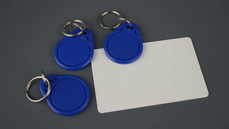
RFID MFRC522 카드 태그 키체인
- 리더/라이터 (근접 결합 장치—PCD)는 태그에 신호를 보내고 그 응답을 읽는 양방향 무선 송수신기입니다.

리더 라이터 RFID MFRC522 모듈
MFRC522 RFID 리더는 3.3V에서 작동하며 SPI 및 I2C 통신 프로토콜을 지원합니다. RFID 리더를 제어하는 데 사용할 라이브러리는 두 프로토콜을 모두 지원하지만, 여기서는 SPI를 사용하겠습니다.
필요한 부품
이 프로젝트에 필요한 구성 요소 목록은 다음과 같습니다.
ESP32 DOIT DEVKIT V1 보드 ( 최고의 ESP32 개발 보드 읽기 )
MFRC522 RFID 리더/라이터 + 태그
브레드보드
점퍼 와이어
Arduino를 사용한 RFID 리더에 대해 자세히 알아보려면 다음을 읽어보세요: Arduino를 사용한 MFRC522 RFID 리더를 사용한 보안 액세스
필수 조건
이 튜토리얼은 아두이노 코어를 사용하여 ESP32를 프로그래밍하는 데 중점을 둡니다. 진행하기 전에 아두이노 IDE에 ESP32 아두이노 코어가 설치되어 있어야 합니다. 아직 아두이노 IDE에 ESP32를 설치하지 않았다면 다음 튜토리얼을 따라 설치하세요.
Arduino_MFRC522v2 라이브러리 설치
이 튜토리얼에서는 다음을 사용합니다.MFRC522v2.hRFID 리더를 제어하는 라이브러리입니다. Arduino IDE에서 "스케치" > "라이브러리 포함" > "라이브러리 관리" 로 이동하거나 왼쪽 사이드바에서 "라이브러리 관리자" 아이콘을 클릭하세요.
MFRC522v2 를 검색 하고 GithubCommunity에서 라이브러리를 설치하세요.

RFID MFRC522v2 라이브러리 Arduino IDE 설치
MFRC522 RFID 리더/라이터 핀아웃 및 ESP32 배선
ESP32 기본 SPI 핀을 사용하여 MFRC522 RFID 리더를 연결하겠습니다. 다음 표를 참고하세요.

리더 라이터 RFID MFRC522 모듈 ESP32 보드 회로
MFRC522 RFID 리더 ESP32 설명
MFRC522 RFID ReaderESP32
| MFRC522 RFID Reader | ESP32 | Description |
| SDA | GPIO 5 | SPI signal input, I2C data line, or UART data input |
| SCK | GPIO 18 | SPI clock |
| MOSI | GPIO 23 | SPI data input |
| MISO | GPIO 19 | SPI master-in-slave-out, I2C serial clock, or UART serial output |
| IRQ | Don’t connect | Interrupt pin; signals the microcontroller when an RFID tag is nearby |
| GND | GND | |
| RST | GPIO 21 | LOW signal to put the module in power-down mode; send a HIGH signal to reset the module |
| 3.3V | 3.3V | Power supply (2.5-3.3V) |
참고: 이 라이브러리는 ESP8266, Arduino 및 기타 보드와도 호환됩니다. 다른 보드를 사용하는 경우 권장 라이브러리 핀 할당을 확인하세요 .
RFID 카드 원시 데이터 읽기 – 코드
다음 예제는 RFID 태그에서 원시 데이터를 읽는 예제입니다. 이 예제를 통해 MIFARE 1K 태그에 데이터가 저장되는 방식을 더 잘 이해할 수 있습니다.
/*
  Rui Santos & Sara Santos - Random Nerd Tutorials
  Complete project details at https://RandomNerdTutorials.com/esp32-mfrc522-rfid-reader-arduino/
  Permission is hereby granted, free of charge, to any person obtaining a copy of this software and associated documentation files.
  The above copyright notice and this permission notice shall be included in all copies or substantial portions of the Software.
*/

#include <MFRC522v2.h>
#include <MFRC522DriverSPI.h>
//#include <MFRC522DriverI2C.h>
#include <MFRC522DriverPinSimple.h>
#include <MFRC522Debug.h>

// Learn more about using SPI/I2C or check the pin assigment for your board: https://github.com/OSSLibraries/Arduino_MFRC522v2#pin-layout
MFRC522DriverPinSimple ss_pin(5);

MFRC522DriverSPI driver{ss_pin}; // Create SPI driver
//MFRC522DriverI2C driver{};     // Create I2C driver
MFRC522 mfrc522{driver};         // Create MFRC522 instance

void setup() {
  Serial.begin(115200);  // Initialize serial communication
  while (!Serial);       // Do nothing if no serial port is opened (added for Arduinos based on ATMEGA32U4).

  mfrc522.PCD_Init();    // Init MFRC522 board.
  MFRC522Debug::PCD_DumpVersionToSerial(mfrc522, Serial);	// Show details of PCD - MFRC522 Card Reader details.
  Serial.println(F("Scan PICC to see UID, SAK, type, and data blocks..."));
}

void loop() {
  // Reset the loop if no new card present on the sensor/reader. This saves the entire process when idle.
  if (!mfrc522.PICC_IsNewCardPresent()) {
    return;
  }

  // Select one of the cards.
  if (!mfrc522.PICC_ReadCardSerial()) {
    return;
  }

  // Dump debug info about the card; PICC_HaltA() is automatically called.
  MFRC522Debug::PICC_DumpToSerial(mfrc522, Serial, &(mfrc522.uid));

  delay(2000);
}
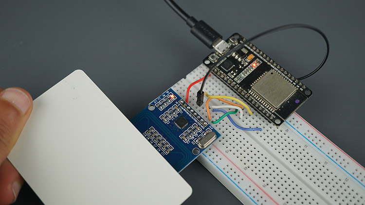
회로를 배선한 후 이전 코드를 보드에 업로드하세요.
업로드 후, 시리얼 모니터를 115200의 전송 속도로 엽니다. 리더기에 태그를 대략적으로 표시하고 태그 정보가 표시되는지 확인합니다.

리더 라이터 RFID MFRC522 모듈 ESP32 카드 리더 키체인
카드 UID, 태그 유형, 메모리 블록이 표시됩니다. 태그는 MIFARE 유형이며 메모리 용량은 1KB입니다.
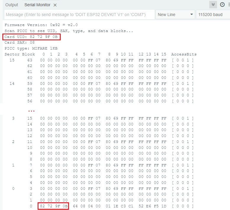
RFID MFRC522v2 라이브러리 섹터 블록 UID 덤프 정보 카드 Arduino IDE 데모 읽기
MIFARE 1K 태그에 데이터가 저장되는 방식에 대해 고려해야 할 몇 가지 필수적인 측면은 다음과 같습니다.
메모리 레이아웃
메모리는 16개의 섹터(0~15)로 구성되며, 각 섹터는 4개의 블록(0~3)으로 나뉘므로 총 64개의 블록이 됩니다. 각 블록은 16바이트(0~15)의 데이터를 저장할 수 있습니다.
제조업체 블록
섹터 0, 블록 0은 UID(처음 4바이트), CRC 검사 바이트, 그리고 제조업체 데이터를 저장합니다. 이 값은 읽기 전용이며 변경할 수 없습니다(UID 변경 가능 카드는 예외). 직렬 모니터 결과에서 볼 수 있듯이 태그의 UUID는 82 72 9F 0B 입니다 .
메모리 스토리지와 섹터 트레일러
각 섹터의 처음 세 블록은 데이터 저장에 사용할 수 있습니다. 각 섹터의 마지막 블록은 섹터 트레일러 입니다 . 이 섹터 트레일러는 두 개의 키 또는 비밀번호를 저장하고 섹터의 나머지 블록에 대한 접근을 제어합니다. 예를 들어, 블록 번호 7은 블록 4, 5, 6을 제어합니다. 이 섹터에 쓰기를 하면 카드가 망가져서 사용할 수 없게 될 수 있습니다.
요약하자면, Mifare 1K 카드의 순 저장 용량은 다음과 같습니다.
(16 sectors/card x 3 data blocks/sector X 16 bytes/block) - 16 bytes (first block) = 752 bytes/card
(16 sectors/card x 3 data blocks/sector X 16 bytes/block) - 16 bytes (first block) = 752 bytes/card
섹터는 16개이고 각 섹터에는 4개의 블록이 있습니다(총 64개의 블록). 각 블록은 16바이트이므로 총 1024바이트(1KB)가 됩니다. 그러나 16개의 블록(각 섹터에 하나씩)은 사용자 데이터가 아닌 액세스 키와 권한을 저장하는 섹터 트레일러입니다. 따라서 사용자 데이터에 사용할 수 있는 블록은 48개입니다. 읽기 전용 제조업체 블록(섹터 0, 블록 0)의 16바이트를 빼면 실제 사용자 저장 공간은 752바이트입니다.
RFID 카드 UID – 코드 읽기
다음 예제는 RFID 태그의 UID만 읽습니다. 저장된 나머지 데이터는 신경 쓰지 않고 카드만 식별하려는 경우 유용할 수 있습니다.
/*
  Rui Santos & Sara Santos - Random Nerd Tutorials
  Complete project details at https://RandomNerdTutorials.com/esp32-mfrc522-rfid-reader-arduino/
  Permission is hereby granted, free of charge, to any person obtaining a copy of this software and associated documentation files.
  The above copyright notice and this permission notice shall be included in all copies or substantial portions of the Software.
*/

#include <MFRC522v2.h>
#include <MFRC522DriverSPI.h>
//#include <MFRC522DriverI2C.h>
#include <MFRC522DriverPinSimple.h>
#include <MFRC522Debug.h>

// Learn more about using SPI/I2C or check the pin assigment for your board: https://github.com/OSSLibraries/Arduino_MFRC522v2#pin-layout
MFRC522DriverPinSimple ss_pin(5);

MFRC522DriverSPI driver{ss_pin}; // Create SPI driver
//MFRC522DriverI2C driver{};     // Create I2C driver
MFRC522 mfrc522{driver};         // Create MFRC522 instance

void setup() {
  Serial.begin(115200);  // Initialize serial communication
  while (!Serial);       // Do nothing if no serial port is opened (added for Arduinos based on ATMEGA32U4).

  mfrc522.PCD_Init();    // Init MFRC522 board.
  MFRC522Debug::PCD_DumpVersionToSerial(mfrc522, Serial);	// Show details of PCD - MFRC522 Card Reader details.
	Serial.println(F("Scan PICC to see UID"));
}

void loop() {
	// Reset the loop if no new card present on the sensor/reader. This saves the entire process when idle.
	if (!mfrc522.PICC_IsNewCardPresent()) {
		return;
	}

	// Select one of the cards.
	if (!mfrc522.PICC_ReadCardSerial()) {
		return;
	}

  Serial.print("Card UID: ");
  MFRC522Debug::PrintUID(Serial, (mfrc522.uid));
  Serial.println();

  // Save the UID on a String variable
  String uidString = "";
  for (byte i = 0; i < mfrc522.uid.size; i++) {
    if (mfrc522.uid.uidByte[i] < 0x10) {
      uidString += "0";
    }
    uidString += String(mfrc522.uid.uidByte[i], HEX);
  }
  Serial.println(uidString);
}
이 코드는 이해하기 매우 간단합니다. setup() 함수에서 먼저 리더를 초기화합니다.
mfrc522.PCD_Init();    // Init MFRC522 board.
MFRC522Debug::PCD_DumpVersionToSerial(mfrc522, Serial);	// Show details of PCD - MFRC522 Card Reader details.
Serial.println(F("Scan PICC to see UID"));
그리고나서 loop 함수에서 카드가 있는지 확인합니다.
// Reset the loop if no new card present on the sensor/reader. This saves the entire process when idle.
if (!mfrc522.PICC_IsNewCardPresent()) {
  return;
}
카드를 읽습니다.
// Select one of the cards.
if (!mfrc522.PICC_ReadCardSerial()) {
  return;
}
마지막으로 UID를 출력하여 변수에 저장합니다.
  Serial.print("Card UID: ");
  MFRC522Debug::PrintUID(Serial, (mfrc522.uid));
  Serial.println();

  // Save the UID on a String variable
  String uidString = "";
  for (byte i = 0; i < mfrc522.uid.size; i++) {
    if (mfrc522.uid.uidByte[i] < 0x10) {
      uidString += "0";
    }
    uidString += String(mfrc522.uid.uidByte[i], HEX);
  }
  Serial.println(uidString);
}
코드를 보드에 업로드하세요. 시리얼 모니터를 115200의 통신 속도로 실행하세요.
리더 라이터 RFID MFRC522 모듈 ESP32 판독 카드
리더기에 다양한 태그를 스와이프하면 고유한 UID가 인쇄되는 것을 볼 수 있습니다.

RFID 카드 UID MFRC522 Arduino IDE 데모 예제 읽기
RFID 카드에 개인 데이터 쓰기/읽기 – 코드
이 예제에서는 특정 블록에 사용자 지정 데이터를 작성하는 방법을 보여드리겠습니다. 그런 다음, 해당 블록에서 데이터를 읽는 방법도 보여드리겠습니다. 아래 코드입니다.
/*
  Rui Santos & Sara Santos - Random Nerd Tutorials
  Complete project details at https://RandomNerdTutorials.com/esp32-mfrc522-rfid-reader-arduino/
  Permission is hereby granted, free of charge, to any person obtaining a copy of this software and associated documentation files.
  The above copyright notice and this permission notice shall be included in all copies or substantial portions of the Software.
*/

#include <MFRC522v2.h>
#include <MFRC522DriverSPI.h>
//#include <MFRC522DriverI2C.h>
#include <MFRC522DriverPinSimple.h>
#include <MFRC522Debug.h>

// Learn more about using SPI/I2C or check the pin assigment for your board: https://github.com/OSSLibraries/Arduino_MFRC522v2#pin-layout
MFRC522DriverPinSimple ss_pin(5);

MFRC522DriverSPI driver{ss_pin}; // Create SPI driver
//MFRC522DriverI2C driver{};     // Create I2C driver
MFRC522 mfrc522{driver};         // Create MFRC522 instance

MFRC522::MIFARE_Key key;

byte blockAddress = 2;
byte newBlockData[17] = {"Rui Santos - RNT"};
//byte newBlockData[16] = {0,0,0,0,0,0,0,0,0,0,0,0,0,0,0,0};   // CLEAR DATA
byte bufferblocksize = 18;
byte blockDataRead[18];

void setup() {
  Serial.begin(115200);  // Initialize serial communication
  while (!Serial);       // Do nothing if no serial port is opened (added for Arduinos based on ATMEGA32U4).

  mfrc522.PCD_Init();    // Init MFRC522 board.
  Serial.println(F("Warning: this example overwrites a block in your card, use with care!"));

  // Prepare key - all keys are set to FFFFFFFFFFFF at chip delivery from the factory.
  for (byte i = 0; i < 6; i++) {
    key.keyByte[i] = 0xFF;
  }
}

void loop() {
  // Check if a new card is present
  if (!mfrc522.PICC_IsNewCardPresent() || !mfrc522.PICC_ReadCardSerial()) {
    delay(500);
    return;
  }

  // Display card UID
  Serial.print("----------------\nCard UID: ");
  MFRC522Debug::PrintUID(Serial, (mfrc522.uid));
  Serial.println();

  // Authenticate the specified block using KEY_A = 0x60
  if (mfrc522.PCD_Authenticate(0x60, blockAddress, &key, &(mfrc522.uid)) != 0) {
    Serial.println("Authentication failed.");
    return;
  }

  // Write data to the specified block
  if (mfrc522.MIFARE_Write(blockAddress, newBlockData, 16) != 0) {
    Serial.println("Write failed.");
  } else {
    Serial.print("Data written successfully in block: ");
    Serial.println(blockAddress);
  }

  // Authenticate the specified block using KEY_A = 0x60
  if (mfrc522.PCD_Authenticate(0x60, blockAddress, &key, &(mfrc522.uid)) != 0) {
    Serial.println("Authentication failed.");
    return;
  }

  // Read data from the specified block
  if (mfrc522.MIFARE_Read(blockAddress, blockDataRead, &bufferblocksize) != 0) {
    Serial.println("Read failed.");
  } else {
    Serial.println("Read successfully!");
    Serial.print("Data in block ");
    Serial.print(blockAddress);
    Serial.print(": ");
    for (byte i = 0; i < 16; i++) {
      Serial.print((char)blockDataRead[i]);  // Print as character
    }
    Serial.println();
  }

  // Halt communication with the card
  mfrc522.PICC_HaltA();
  mfrc522.PCD_StopCrypto1();

  delay(2000);  // Delay for readability
}
코드는 어떻게 작동하나요?
RFID 리더를 설정하는 데 필요한 라이브러리를 포함하는 것으로 시작합니다.
#include <MFRC522v2.h>
#include <MFRC522DriverSPI.h>
//#include <MFRC522DriverI2C.h>
#include <MFRC522DriverPinSimple.h>
#include <MFRC522Debug.h>
CS(칩 선택) 핀을 핀 5로 정의하며, 이 핀은 리더와의 SPI 통신에 사용됩니다.
// Learn more about using SPI/I2C or check the pin assigment for your board: https://github.com/OSSLibraries/Arduino_MFRC522v2#pin-layout
MFRC522DriverPinSimple ss_pin(5);

MFRC522DriverSPI driver{ss_pin}; // Create SPI driver
//MFRC522DriverI2C driver{};     // Create I2C driver
MFRC522 mfrc522{driver};         // Create MFRC522 instance

MFRC522::MIFARE_Key key;
그런 다음 blockAddress라는 변수를 정의합니다. 이 변수는 RFID 태그에서 데이터가 쓰여지거나 읽힐 블록을 지정합니다. 이 예시에서 blockAddress는 2로 설정되어 있어, 코드가 카드 메모리의 블록 2와 상호작용함을 의미합니다. 다른 블록에 쓰기를 원한다면 이 값을 변경할 수 있습니다.
byte blockAddress = 2;
중요: 각 섹터의 마지막 블록은 섹터 트레일러 입니다 . 해당 섹터에는 쓰지 마세요. 그렇지 않으면 카드가 망가질 수 있습니다.
다음으로, newBlockData[17]에는 카드에 기록할 데이터가 저장됩니다. 현재는 Rui Santos – RNT로 설정되어 있지만 변경할 수 있습니다. 데이터 길이가 16바이트를 초과하지 않도록 주의하십시오.
byte newBlockData[17] = {"Rui Santos - RNT"};
블록 데이터를 지우려면 다음 바이트 배열을 전달하면 됩니다.
byte newBlockData[16] = {0,0,0,0,0,0,0,0,0,0,0,0,0,0,0,0};
setup 함수에서 MFRC522 모듈을 초기화합니다.
mfrc522.PCD_Init(); // Init MFRC522 board.
RFID 카드의 기본 키도 다음 줄에 설정됩니다. 기본적으로 모든 바이트는 0xFF 생산 키입니다. 이 키를 사용하면 카드의 데이터 블록에 접근할 수 있습니다.
// Prepare key - all keys are set to FFFFFFFFFFFF at chip delivery from the factory.
for (byte i = 0; i < 6; i++) {
  key.keyByte[i] = 0xFF;
}
loop 함수에서 새로운 RFID 카드가 감지되었는지 확인합니다. 카드가 있으면 카드의 UID를 읽고 표시합니다.
if (!mfrc522.PICC_IsNewCardPresent() || !mfrc522.PICC_ReadCardSerial()) {
  delay(500);
  return;
}

// Display card UID
Serial.print("----------------\nCard UID: ");
MFRC522Debug::PrintUID(Serial, (mfrc522.uid));
Serial.println();
다음으로, 코드는 기본 키를 사용하여 카드의 특정 블록(이 경우 블록 2)을 인증하려고 시도합니다.
// Authenticate the specified block using KEY_A = 0x60
if (mfrc522.PCD_Authenticate(0x60, blockAddress, &key, &(mfrc522.uid)) != 0) {
  Serial.println("Authentication failed.");
  return;
}
참고: 0x60은 인증에 KEY_A 사용을 지정하는 명령어입니다. KEY_A는 RFID 카드에 탑재된 두 개의 키(KEY_A와 KEY_B) 중 하나로, 각각 다른 권한을 제공합니다. 0x60을 사용한다는 것은 코드가 KEY_A로 인증을 시도함을 의미하며, MIFARE RFID 카드에서는 기본값이 0xFF 0xFF 0xFF 0xFF 0xFF입니다.
인증이 성공하면, 해당 블록에 일부 데이터(newBlockData에 저장됨)를 기록합니다.
쓰기가 끝나면 블록에서 데이터를 다시 읽어서 직렬 모니터에 출력합니다.
// Write data to the specified block
if (mfrc522.MIFARE_Write(blockAddress, newBlockData, 16) != 0) {
  Serial.println("Write failed.");
} else {
  Serial.print("Data written successfully in block: ");
  Serial.println(blockAddress);
}
쓰기 작업 후, 블록에서 데이터를 다시 읽어와 시리얼 모니터에 출력합니다.
// Read data from the specified block
if (mfrc522.MIFARE_Read(blockAddress, blockDataRead, &bufferblocksize) != 0) {
  Serial.println("Read failed.");
} else {
  Serial.println("Read successfully!");
  Serial.print("Data in block ");
  Serial.print(blockAddress);
  Serial.print(": ");
  for (byte i = 0; i < 16; i++) {
    Serial.print((char)blockDataRead[i]);  // Print as character
  }
  Serial.println();
}
마지막으로, 코드는 카드와의 통신을 중단하고 암호화를 중단합니다.
// Halt communication with the card
mfrc522.PICC_HaltA();
mfrc522.PCD_StopCrypto1();
예제 테스트
이 예에서 우리는 두 개의 서로 다른 RFID 카드의 블록 번호 2에 "Rui Santos – RNT"라는 개인 데이터를 저장했습니다.
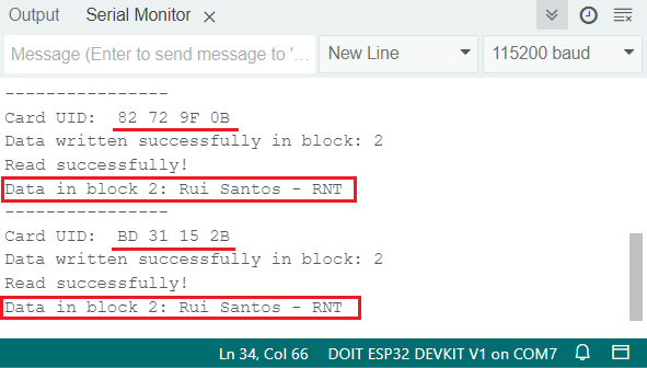
RFID MFRC522v2 라이브러리 개인 데이터 섹터 블록 읽기 Arduino IDE 데모
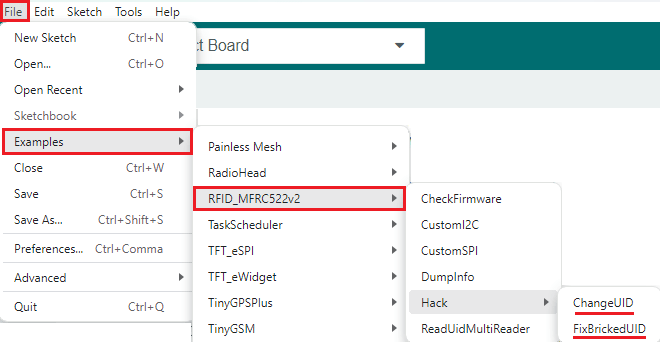
다른 유용한 예
Arduino_MFRC522v2 라이브러리와 함께 제공되는 예제 중 도움이 될 만한 몇 가지가 있습니다. Hack 하위 메뉴에서 ChangeUID 및 FixBrickedUID 예제를 찾을 수 있습니다.
중요: 대부분의 RFID 카드는 UID 수정을 허용하지 않습니다. 이 코드는 쓰기 가능한 UID 블록을 가진 특정 MIFARE Classic 카드에서만 작동합니다. 대부분의 RFID 카드는 UID가 읽기 전용으로 설정되어 있으므로, UID를 변경하려고 하면 작동하지 않습니다.
RFID MFRC522v2 라이브러리 예제 Arduino IDE
마무리하기
이 가이드에서는 MFRC522 RFID 리더/라이터 모듈을 ESP32와 연결하는 방법을 알아보았습니다. Mifare 1K 카드의 저장 방식과 카드에서 정보를 추출하는 방법을 살펴보았습니다. 또한 카드 UID를 가져오고, 특정 블록에 새 데이터를 쓰고, 특정 블록에서 데이터를 읽는 방법도 알아보았습니다.
ESP32와 MFRC522 RFID 리더/라이터에 대한 이 가이드가 도움이 되었기를 바랍니다. 아두이노 보드에 대한 유사한 가이드도 있습니다.
Arduino를 사용한 MFRC522 RFID 리더를 사용한 보안 액세스
여기까지 수고하셨습니다. 시간내서 읽어주셔서 감사합니다. 본 튜토리얼의 원문은 다음 링크를 참고하세요.
LVGL 라이브러리를 사용하여 CYD MicroSD 슬롯의 SPI를 통해 RC522 RF IC 카드 센서 모듈을 제어하는 동시에 CYD 화면과 터치스크린도 사용할 수 있었습니다.
관심 있으시면 다음 링크에서 자세한 내용을 확인하실 수 있습니다:
https://github.com/Mark-MDO47/UniRemote/blob/master/code/RFIDRC522test/README.md
https://randomnerdtutorials.com/esp32-mfrc522-rfid-reader-arduino/#:~:text=다음 예제는 RFID 태그에서 원시 데이터를 읽습니다. 이 예제를 통해 MIFARE1K 태그에 데이터가 저장되는 방식을 더 잘 이해할 수 있습니다 .
제가 조사해 본 결과 RC522 기반 센서 모듈은 컨트롤러 칩 자체에는 I2C 기능이 있다고 명시되어 있지만, 실제로는 I2C 통신이 가능하도록 핀이 연결되어 있지 않은 것 같습니다. 기판을 개조하면 작동하도록 만들 수 있을지도 모르지만, 저는 시도해 보지 않았습니다.
위 정보는 제가 찾은 자료이니 직접 확인해 보시고 제가 잘못 이해하고 있는 부분이 있는지 살펴보세요. 2023년 3월에 작성된 Adrianotiger의 4번 게시글( https://forum.arduino.cc/t/esp32-rfid-rc522-i2c/1100200/3
)을 참고해 보세요.
'ESP32' 카테고리의 다른 글
| ESP32 펌웨어 크기로 OTA 안되는 문제 해결방법 (0) | 2025.12.16 |
|---|---|
| ESP32 OTA 자동 업데이터 (0) | 2025.12.15 |
| ESP32 제품군 설명: 기술적 차이점과 각 제품의 적용 분야 (1) | 2025.12.14 |
| Xiao ESP32 S3를 사용한 지오펜스 기능이 있는 GPS 추적기 Seeed Studio (2) | 2025.12.12 |
| ESP32 RFID 리더기 UART 데이터 읽기 125KHz, 13.56MHz (0) | 2025.12.10 |
| ESP32 유용한 Wi-Fi 라이브러리 함수(Arduino IDE) (1) | 2025.12.04 |
| ESP32 SIM800L 및 NEO-6M 모듈을 사용한 GPS 추적기 (1) | 2025.12.04 |
| Arduino IDE와 ESP-IDF 개발 환경 비교 (0) | 2025.12.02 |
취업, 창업의 막막함, 외주 관리, 제품 부재!
당신의 고민은 무엇입니까? 현실과 동떨어진 교육, 실패만 반복하는 외주 계약,
아이디어는 있지만 구현할 기술이 없는 막막함.
우리는 알고 있습니다. 문제의 원인은 '명확한 학습, 실전 경험과 신뢰할 수 있는 기술력의 부재'에서 시작됩니다.
이제 고민을 멈추고, 캐어랩을 만나세요!
코딩(펌웨어), 전자부품과 디지털 회로설계, PCB 설계 제작, 고객(시장/수출) 발굴과 마케팅 전략으로 당신을 지원합니다.
제품 설계의 고수는 성공이 만든 게 아니라 실패가 만듭니다. 아이디어를 양산 가능한 제품으로!
귀사의 제품을 만드세요. 교육과 개발 실적으로 신뢰할 수 있는 파트너를 확보하세요.
캐어랩


