Arduino를 사용하는 RS-485 구현
MAX485 모듈을 사용하여 두 Arduino 간의 통신에서 RS-485 프로토콜을 구현합니다.
RS-485는 데이터와 함께 전송되는 동기화 클럭 신호가 없기 때문에 비동기 직렬 통신 프로토콜의 한 유형입니다. RS-485는 차동 신호를 사용하여 한 장치에서 다른 장치로 이진 데이터를 전송합니다. 차동 신호는 5V 양과 음을 사용하여 차동 전압을 생성하여 작동했습니다. 이 차동 신호 방법은 공통 모드 노이즈를 거부하는 이점이 있습니다.
RS-485는 최대 30 Mbps의 데이터 전송 속도를 지원합니다. RS-485는 또한 단일 마스터로 많은 슬레이브를 지원합니다. RS-485 프로토콜은 최대 32개의 장치를 연결할 수 있습니다.
이 프로젝트에서는 MAX485 모듈을 사용하여 두 Arduino 간의 통신에서 RS-485 프로토콜을 구현하려고 합니다. 이 모듈은 작동 전압으로 5V를 사용하며 다음 표와 같이 핀아웃 구성이 있습니다.


RS-485 모듈을 송신기로
송신기로 사용하기 위해서는 RE 핀과 DE 핀을 5V에 연결하고 DI 핀을 TX에 연결해야 합니다. 데이터는 Arduino TX 핀에서 모듈 DI 핀으로 전송되고 데이터는 A, B를 통해 전송됩니다.
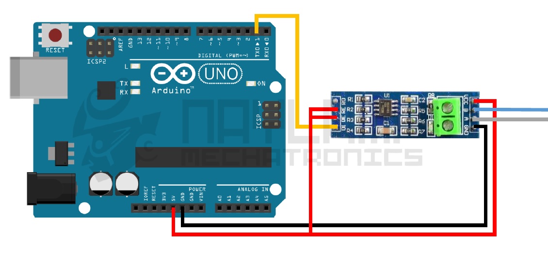
void setup()
{
  Serial.begin(9600);
}

void loop()
{
  int lectura = analogRead(0);//leemos el valor del potenciómetro (de 0 a 1023)
  byte angulo= map(lectura, 0, 1023, 0, 180);     // escalamos la lectura a un valor de ángulo (entre 0 y 180)
  Serial.write(angulo); //enviamos el ángulo correspondiente
  delay(50);
}
수신기로서의 RS-485 모듈
수신기로 사용하기 위해서는 RE 핀과 DE 핀을 GND에 연결하고 RO 핀을 RX에 연결해야 합니다. AB에서 수신한 데이터는 Arduino RX 핀에 연결된 RO 핀으로 전송되어 Arduino에서 데이터를 읽을 수 있습니다. RS-485는 단방향, 반이중 및 전이중의 세 가지 유형의 직렬 통신 시스템으로 구현할 수 있습니다.
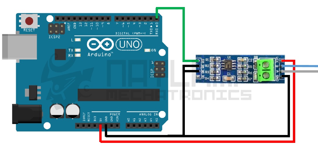
#include <Servo.h>

Servo myservo;  // creamos el objeto servo

void setup()
{
  Serial.begin(9600);
  myservo.attach(9);  // asignamos el pin 9 para el servo.
}

void loop()
{

  if (Serial.available()) {
    int angulo = Serial.read(); //Leemos el dato recibido
    if(angulo<=180) //verificamos que sea un valor en el rango del servo
    {
      myservo.write(angulo); //movemos el servomotor al ángulo correspondiente.
    }
  }
}
RS485를 통한 두 Arduino 간의 Simplex Communication
Simplex 통신은 단방향 통신(하나는 데이터를 보내고 다른 하나는 데이터만 수신)으로, 하나의 arduino는 송신기로만 작동하고 다른 하나는 수신기로만 작동합니다. 이 실험에서 송신기는 전위차계에서 데이터를 읽어 수신기에 연결된 서보 모터를 제어합니다. 동작 코드는 위의 송신기 동작 코드와 수신기 동작 코드를 사용하시면 동작합니다.
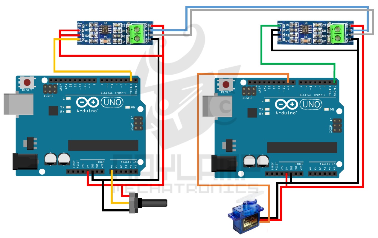
RS485를 통한 두 Arduino 간의 Half-duplex 통신
반이중 통신은 데이터를 동시에 주고받을 수 없는 한 채널을 사용하는 양방향 통신입니다. 두 arduino 모두 GPIO 핀에 의해 제어되는 송신기 또는 수신기로 교대로 동작합니다(HIGH는 송신기로 활성화하고 LOW는 수신기로 활성화).
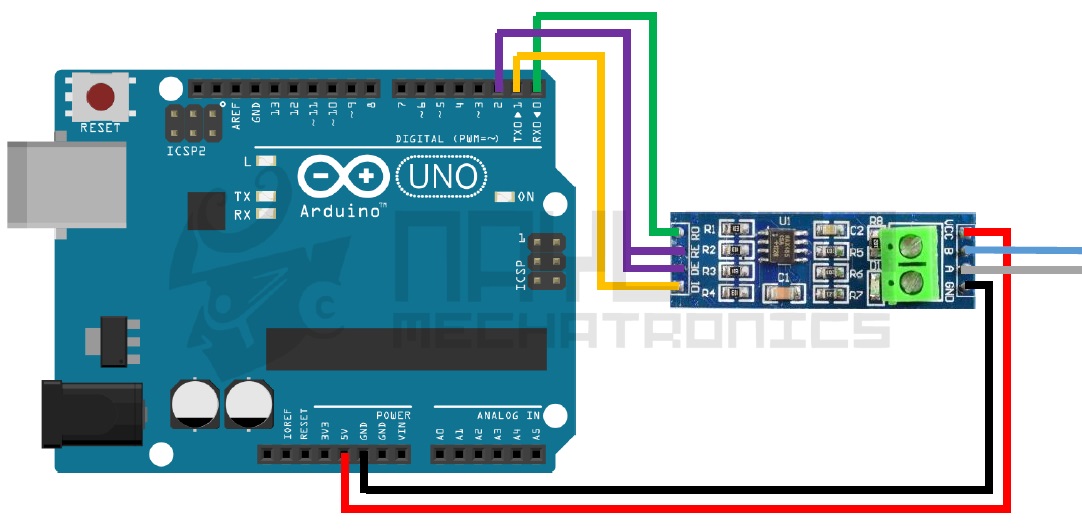
반이중 통신에서는 단일 채널을 사용하여 통신합니다. 한 지점에서는 채널을 통해 데이터가 전송되고 다른 순간에는 데이터가 수신되지만 동시에 송수신할 수는 없습니다. 이 통신을 수행하려면 RS485 모듈의 DE 및 RE 핀을 Arduino에 연결해야 합니다. 이를 통해 프로그램에서 모듈을 송신기 또는 수신기로 설정할 수 있습니다.
이 실험에서 Arduino 1은 Arduino 2에 연결된 서보 모터를 제어하기 위해 전위차계에서 데이터를 읽을 뿐만 아니라 Arduino 2에 연결된 센서(전위차계로 표시됨)에서 데이터를 수신한 다음 데이터가 임계값에 도달했습니다. 연결은 아래와 같습니다.
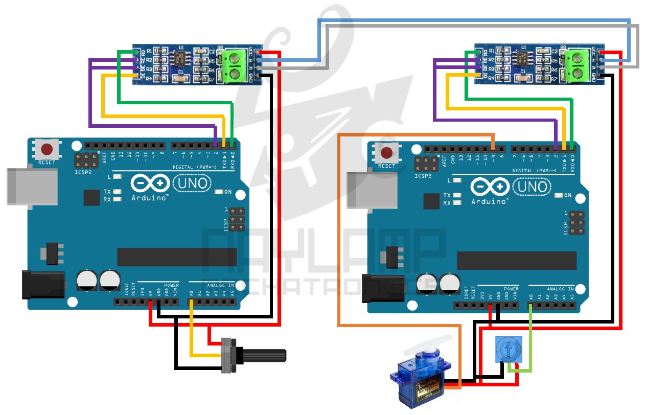
왼쪽의 아두이노는 Master가 되고, 오른쪽의 Arduino는 슬레이브가 됩니다. 코드를 마스터와 슬레이브 둘 다 표시합니다.
마스터 코드
const int ledPin =  13;  // Numero del pin para el Led
const int EnTxPin =  2;  // HIGH:TX y LOW:RX
void setup()
{
  Serial.begin(9600);
  Serial.setTimeout(100);//establecemos un tiempo de espera de 100ms
  //inicializamos los pines
  pinMode(ledPin, OUTPUT);
  pinMode(EnTxPin, OUTPUT);
  digitalWrite(ledPin, LOW);
  digitalWrite(EnTxPin, HIGH);
}

void loop()
{

  int lectura = analogRead(0);//leemos el valor del potenciómetro (de 0 a 1023)
  int angulo= map(lectura, 0, 1023, 0, 180);// escalamos la lectura a un valor de ángulo (entre 0 y 180)
  //---enviamos el ángulo para mover el servo------
  Serial.print("I"); //inicio de trama
  Serial.print("S"); //S para indicarle que vamos a mover el servo
  Serial.print(angulo); //ángulo  o dato
  Serial.print("F"); //fin de trama
  //----------------------------
  delay(50);
  //---solicitamos una lectura del sensor----------
  Serial.print("I"); //inicio de trama
  Serial.print("L"); //L para indicarle que vamos a Leer el sensor
  Serial.print("F"); //fin de trama
  Serial.flush();    //Esperamos hasta que se envíen los datos
  //----Leemos la respuesta del Esclavo-----
  digitalWrite(EnTxPin, LOW); //RS485 como receptor
  if(Serial.find("i"))//esperamos el inicio de trama
  {
      int dato=Serial.parseInt(); //recibimos valor numérico
      if(Serial.read()=='f') //Si el fin de trama es el correcto
       {
         funcion(dato);  //Realizamos la acción correspondiente
      }

  }
  digitalWrite(EnTxPin, HIGH); //RS485 como Transmisor
  //----------fin de la respuesta-----------

}
void funcion(int dato)
{
  if(dato>500)
  digitalWrite(ledPin, HIGH);
  else
  digitalWrite(ledPin, LOW);
}
슬레이브 코드
#include <Servo.h>

Servo myservo;  // creamos el objeto servo
const int EnTxPin =  2;
void setup()
{
  Serial.begin(9600);
  myservo.attach(9);  // asignamos el pin 9 para el servo.
  pinMode(EnTxPin, OUTPUT);
  digitalWrite(EnTxPin, LOW); //RS485 como receptor
}

void loop()
{
  if(Serial.available())
  {
    if(Serial.read()=='I') //Si recibimos el inicio de trama
    {

      char funcion=Serial.read();//leemos el carácter de función
      //---Si el carácter de función es una S entonces la trama es para mover el motor-----------
      if(funcion=='S')
       {
           int angulo=Serial.parseInt(); //recibimos el ángulo
           if(Serial.read()=='F') //Si el fin de trama es el correcto
           {
             if(angulo<=180) //verificamos que sea un valor en el rango del servo
              {
                myservo.write(angulo); //movemos el servomotor al ángulo correspondiente.
              }
           }
       }
       //---Si el carácter de función  es L entonces el maestro está solicitando una lectura del sensor---
       else if(funcion=='L')
       {
          if(Serial.read()=='F') //Si el fin de trama es el correcto
           {
             int lectura = analogRead(0);  //realizamos  la lectura del sensor
             digitalWrite(EnTxPin, HIGH);  //rs485 como transmisor
             Serial.print("i"); //inicio de trama
             Serial.print(lectura); //valor del sensor
             Serial.print("f"); //fin de trama
             Serial.flush(); //Esperamos hasta que se envíen los datos
             digitalWrite(EnTxPin, LOW); //RS485 como receptor
           }
       }
    }
  }
  delay(10);
}
참고
COMUNICACIÓN RS485 CON ARDUINO
위 사이트를 참고하여 전체를 다시 포스팅하기로~^^
'개발자 > Arduino' 카테고리의 다른 글
| Nano 33 IoT 보드 IoT Application (0) | 2022.02.16 |
|---|---|
| Adafruit Feather nRF52840 05. 씨리얼 포트 인식 해결 (0) | 2022.02.11 |
| Adafruit Feather nRF52840 Express 04. Bootloader Update (0) | 2022.02.08 |
| Adafruit Feather nRF52840 Express 03. Arduino IDE 환경 설정 (0) | 2022.02.07 |
| Adafruit Feather nRF52840 Express 02. Hardware 설계와 참고자료 (0) | 2021.12.08 |
| Adafruit Feather nRF52840 Express 01. 소개 (0) | 2021.12.06 |
| Arduino 와 Processing 나침반 만들기 (0) | 2021.11.11 |
| Adafruit TCS34725 컬러 센서로 빛과 색상 측정 (0) | 2021.11.01 |
취업, 창업의 막막함, 외주 관리, 제품 부재!
당신의 고민은 무엇입니까? 현실과 동떨어진 교육, 실패만 반복하는 외주 계약,
아이디어는 있지만 구현할 기술이 없는 막막함.
우리는 알고 있습니다. 문제의 원인은 '명확한 학습, 실전 경험과 신뢰할 수 있는 기술력의 부재'에서 시작됩니다.
이제 고민을 멈추고, 캐어랩을 만나세요!
코딩(펌웨어), 전자부품과 디지털 회로설계, PCB 설계 제작, 고객(시장/수출) 발굴과 마케팅 전략으로 당신을 지원합니다.
제품 설계의 고수는 성공이 만든 게 아니라 실패가 만듭니다. 아이디어를 양산 가능한 제품으로!
귀사의 제품을 만드세요. 교육과 개발 실적으로 신뢰할 수 있는 파트너를 확보하세요.
캐어랩


