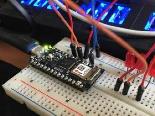
이 데모에서는 간단한 IoT 애플리케이션을 실행합니다. 3개의 LED를 사용합니다. 예제에서는 같은 네트워크에서 HTTP 요청을 Nano 33 IoT 보드에 다음과 같이 정의합니다.
- http:///gpio1/1 turns on LED 1
- http:///gpio1/0 turns off LED 1
- http:///gpio2/1 turns on LED 2
- http:///gpio2/0 turns off LED 2
- http:///gpio3/1 turns on LED 3
- http:///gpio3/0 turns off LED 3
브레드 보드에 LED3 개를 다음과 같이 연결합니다.
- LED 1 is connected to digital pin 6
- LED 2 is connected to digital pin 4
- LED 3 is connected to digital pin 3

아래 소스코드를 iotdemo.ino 파일로 저장하고, 컴파일 업로드 하세요.
#include <SPI.h>
#include <WiFiNINA.h>

int led1 = 6;
int led2 = 4;
int led3 = 3;

const char* ssid = "ssid";
const char* password = "ssid_key";

int status = WL_IDLE_STATUS;

WiFiServer server(80);

void setup() {
	Serial.begin(9600);
	delay(10);

	// prepare GPIO5
	pinMode(led1, OUTPUT);
	pinMode(led2, OUTPUT);
	pinMode(led3, OUTPUT);
	digitalWrite(led1, 0);
	digitalWrite(led2, 0);
	digitalWrite(led3, 0);

	// Connect to WiFi network
	while (status != WL_CONNECTED) {
		Serial.print("Attempting to connect to SSID: ");
		Serial.println(ssid);
		status = WiFi.begin(ssid, password);

		// wait 10 seconds for connection:
		delay(10000);
	}
	Serial.println("");
	Serial.println("WiFi connected");

	// Start the server
	server.begin();
	Serial.println("Server started");

	// Print the IP address
	char ips[24];
	IPAddress ip = WiFi.localIP();
	sprintf(ips, "%d.%d.%d.%d", ip[0], ip[1], ip[2], ip[3]);
	Serial.println(ips);
}

void loop() {
	// Check if a client has connected
	WiFiClient client = server.available();
	if (!client) {
		return;
	}

	// Wait until the client sends some data
	Serial.println("new client");
	while(!client.available()){
	delay(1);
	}

	// Read the first line of the request
	String req = client.readStringUntil('\r');
	Serial.println(req);
	client.flush();

	// Match the request
	int val1 = 0;
	int val2 = 0;
	int val3 = 0;
	int ledreq = 0;
	if (req.indexOf("/gpio1/0") != -1) {
		val1 = 0;
		ledreq = 1;
	}
	else if (req.indexOf("/gpio1/1") != -1) {
		val1 = 1;
		ledreq = 1;
	}
	else if (req.indexOf("/gpio2/0") != -1) {
		val2 = 0;
		ledreq = 2;
	}
	else if (req.indexOf("/gpio2/1") != -1) {
		val2 = 1;
		req = 2;
	}
	else if (req.indexOf("/gpio3/0") != -1) {
		val3 = 0;
		ledreq = 3;
	}
	else if (req.indexOf("/gpio3/1") != -1) {
		val3 = 1;
		ledreq = 3;
	}
	else {
		Serial.println("invalid request");
		client.stop();
		return;
	}

	// Set GPIO2 according to the request
	digitalWrite(led1, val1);
	digitalWrite(led2, val2);
	digitalWrite(led3, val3);
	client.flush();

	// Prepare the response
	String s = "HTTP/1.1 200 OK\r\nContent-Type: text/html\r\n\r\n<!DOCTYPE HTML>"
    if(ledreq==1) {
		s += "LED1 is ";
		s += (val1)? "ON": "OFF";
	}else if(ledreq==2) {
		s += "LED2 is ";
		s += (val2)? "ON": "OFF";
	}else if(ledreq==3) {
		s += "LED3 is ";
		s += (val3)? "ON": "OFF";
	}
	s += "</html>\n";
	// Send the response to the client
	client.print(s);
	delay(1);
	client.stop();
	Serial.println("Client disonnected");
}
테스트
프로그램을 컴파일하고 Arduino 보드에 업로드하십시오. 직렬 모니터를 엽니다. 시리얼 모니터에 아두이노의 IP 주소가 보일 때까지 기다리세요.

브라우저를 엽니다. 이제 브라우저 주소창에 명령어를 입력하여 http:///gpio3/1로 이동하여 LED3을 켜고 끌 수 있습니다.


또한 직렬 모니터에서 응답을 볼 수 있습니다. LED3도 켜져 있어야 합니다.
참고
ESP8266 기본 예제 http 통신
'개발자 > Arduino' 카테고리의 다른 글
| 4 Digit 7 Segment Display 아두이노 제어 (0) | 2022.03.31 |
|---|---|
| 아두이노 버튼처리 한번, 버튼 길게, 더블 클릭 감지하기 (0) | 2022.03.09 |
| ATtiny13a 기반 가장 작은 제어 시스템 (0) | 2022.03.03 |
| Arduino 에서 ATtiny13, ATtiny13a 프로그래밍하는 방법 (0) | 2022.02.18 |
| Adafruit Feather nRF52840 05. 씨리얼 포트 인식 해결 (0) | 2022.02.11 |
| Adafruit Feather nRF52840 Express 04. Bootloader Update (0) | 2022.02.08 |
| Adafruit Feather nRF52840 Express 03. Arduino IDE 환경 설정 (0) | 2022.02.07 |
| Arduino를 사용하는 RS-485 구현 (0) | 2021.12.13 |
취업, 창업의 막막함, 외주 관리, 제품 부재!
당신의 고민은 무엇입니까? 현실과 동떨어진 교육, 실패만 반복하는 외주 계약,
아이디어는 있지만 구현할 기술이 없는 막막함.
우리는 알고 있습니다. 문제의 원인은 '명확한 학습, 실전 경험과 신뢰할 수 있는 기술력의 부재'에서 시작됩니다.
이제 고민을 멈추고, 캐어랩을 만나세요!
코딩(펌웨어), 전자부품과 디지털 회로설계, PCB 설계 제작, 고객(시장/수출) 발굴과 마케팅 전략으로 당신을 지원합니다.
제품 설계의 고수는 성공이 만든 게 아니라 실패가 만듭니다. 아이디어를 양산 가능한 제품으로!
귀사의 제품을 만드세요. 교육과 개발 실적으로 신뢰할 수 있는 파트너를 확보하세요.
캐어랩


