반응형
이 데모에서는 간단한 IoT 애플리케이션을 실행합니다. 3개의 LED를 사용합니다. 예제에서는 같은 네트워크에서 HTTP 요청을 Nano 33 IoT 보드에 다음과 같이 정의합니다.
- http:///gpio1/1 turns on LED 1
- http:///gpio1/0 turns off LED 1
- http:///gpio2/1 turns on LED 2
- http:///gpio2/0 turns off LED 2
- http:///gpio3/1 turns on LED 3
- http:///gpio3/0 turns off LED 3
브레드 보드에 LED3 개를 다음과 같이 연결합니다.
- LED 1 is connected to digital pin 6
- LED 2 is connected to digital pin 4
- LED 3 is connected to digital pin 3

아래 소스코드를 iotdemo.ino 파일로 저장하고, 컴파일 업로드 하세요.
#include <SPI.h>
#include <WiFiNINA.h>

int led1 = 6;
int led2 = 4;
int led3 = 3;

const char* ssid = "ssid";
const char* password = "ssid_key";

int status = WL_IDLE_STATUS;

WiFiServer server(80);

void setup() {
	Serial.begin(9600);
	delay(10);

	// prepare GPIO5
	pinMode(led1, OUTPUT);
	pinMode(led2, OUTPUT);
	pinMode(led3, OUTPUT);
	digitalWrite(led1, 0);
	digitalWrite(led2, 0);
	digitalWrite(led3, 0);

	// Connect to WiFi network
	while (status != WL_CONNECTED) {
		Serial.print("Attempting to connect to SSID: ");
		Serial.println(ssid);
		status = WiFi.begin(ssid, password);

		// wait 10 seconds for connection:
		delay(10000);
	}
	Serial.println("");
	Serial.println("WiFi connected");

	// Start the server
	server.begin();
	Serial.println("Server started");

	// Print the IP address
	char ips[24];
	IPAddress ip = WiFi.localIP();
	sprintf(ips, "%d.%d.%d.%d", ip[0], ip[1], ip[2], ip[3]);
	Serial.println(ips);
}

void loop() {
	// Check if a client has connected
	WiFiClient client = server.available();
	if (!client) {
		return;
	}

	// Wait until the client sends some data
	Serial.println("new client");
	while(!client.available()){
	delay(1);
	}

	// Read the first line of the request
	String req = client.readStringUntil('\r');
	Serial.println(req);
	client.flush();

	// Match the request
	int val1 = 0;
	int val2 = 0;
	int val3 = 0;
	int ledreq = 0;
	if (req.indexOf("/gpio1/0") != -1) {
		val1 = 0;
		ledreq = 1;
	}
	else if (req.indexOf("/gpio1/1") != -1) {
		val1 = 1;
		ledreq = 1;
	}
	else if (req.indexOf("/gpio2/0") != -1) {
		val2 = 0;
		ledreq = 2;
	}
	else if (req.indexOf("/gpio2/1") != -1) {
		val2 = 1;
		req = 2;
	}
	else if (req.indexOf("/gpio3/0") != -1) {
		val3 = 0;
		ledreq = 3;
	}
	else if (req.indexOf("/gpio3/1") != -1) {
		val3 = 1;
		ledreq = 3;
	}
	else {
		Serial.println("invalid request");
		client.stop();
		return;
	}

	// Set GPIO2 according to the request
	digitalWrite(led1, val1);
	digitalWrite(led2, val2);
	digitalWrite(led3, val3);
	client.flush();

	// Prepare the response
	String s = "HTTP/1.1 200 OK\r\nContent-Type: text/html\r\n\r\n<!DOCTYPE HTML>"
    if(ledreq==1) {
		s += "LED1 is ";
		s += (val1)? "ON": "OFF";
	}else if(ledreq==2) {
		s += "LED2 is ";
		s += (val2)? "ON": "OFF";
	}else if(ledreq==3) {
		s += "LED3 is ";
		s += (val3)? "ON": "OFF";
	}
	s += "</html>\n";
	// Send the response to the client
	client.print(s);
	delay(1);
	client.stop();
	Serial.println("Client disonnected");
}
테스트
프로그램을 컴파일하고 Arduino 보드에 업로드하십시오. 직렬 모니터를 엽니다. 시리얼 모니터에 아두이노의 IP 주소가 보일 때까지 기다리세요.

브라우저를 엽니다. 이제 브라우저 주소창에 명령어를 입력하여 http:///gpio3/1로 이동하여 LED3을 켜고 끌 수 있습니다.

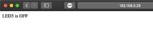
또한 직렬 모니터에서 응답을 볼 수 있습니다. LED3도 켜져 있어야 합니다.
참고
ESP8266 기본 예제 http 통신
반응형
'개발자 > Arduino' 카테고리의 다른 글
| 4 Digit 7 Segment Display 아두이노 제어 (0) | 2022.03.31 |
|---|---|
| 아두이노 버튼처리 한번, 버튼 길게, 더블 클릭 감지하기 (0) | 2022.03.09 |
| ATtiny13a 기반 가장 작은 제어 시스템 (0) | 2022.03.03 |
| Arduino 에서 ATtiny13, ATtiny13a 프로그래밍하는 방법 (0) | 2022.02.18 |
| Adafruit Feather nRF52840 05. 씨리얼 포트 인식 해결 (0) | 2022.02.11 |
| Adafruit Feather nRF52840 Express 04. Bootloader Update (0) | 2022.02.08 |
| Adafruit Feather nRF52840 Express 03. Arduino IDE 환경 설정 (0) | 2022.02.07 |
| Arduino를 사용하는 RS-485 구현 (0) | 2021.12.13 |
더욱 좋은 정보를 제공하겠습니다.~ ^^


