ESP32 LED 제어 웹 서버
이 프로젝트에서는 Arduino IDE 프로그래밍 환경을 사용하여 출력(두 개의 LED)을 제어하는 ESP32가 있는 독립형 웹 서버를 만듭니다. 웹 서버는 모바일 반응형이며 로컬 네트워크의 브라우저로 모든 기기에서 액세스할 수 있습니다. 웹 서버를 만드는 방법과 코드가 단계별로 작동하는 방식을 보여드리겠습니다.

ESP32에 대해 자세히 알아보려면 ESP32 시작 가이드를 읽어보세요 .
비디오 튜토리얼을 시청하세요. 이 튜토리얼은 비디오 형식(아래에서 시청)과 서면 형식(이 페이지를 계속 읽어보세요)으로 제공됩니다.
프로젝트 개요
프로젝트를 바로 시작하기 전에 웹 서버가 무엇을 할 것인지 개략적으로 설명하는 것이 중요합니다. 이렇게 하면 나중에 단계를 따라가기가 더 쉽습니다.
- 당신이 만들 웹 서버는 ESP32에 연결된 두 개의 LED를 제어합니다.GPIO 26그리고 GPIO 27;
- 로컬 네트워크의 브라우저에 ESP32 IP 주소를 입력하여 ESP32 웹 서버에 액세스할 수 있습니다.
- 웹 서버의 버튼을 클릭하면 각 LED의 상태를 즉시 변경할 수 있습니다.
이는 출력을 제어하는 웹 서버를 만드는 방법을 설명하기 위한 간단한 예일 뿐입니다. 아이디어는 해당 LED를 릴레이 나 원하는 다른 전자 부품으로 바꾸는 것입니다.
Arduino IDE에 ESP32 보드 설치
Arduino IDE용 애드온이 있는데, 이를 사용하면 Arduino IDE와 해당 프로그래밍 언어를 사용하여 ESP32를 프로그래밍할 수 있습니다. 다음 튜토리얼 중 하나를 따라 Arduino IDE를 준비하세요.
필요한 부품
이 튜토리얼을 진행하려면 다음 부품이 필요합니다.

- ESP32 개발 보드 - ESP32 개발 보드 리뷰 및 비교 읽기
- 2x 5mm LED
- 2x 330 옴 저항기
- 브레드보드
- 점퍼 와이어
이전 링크를 사용하거나 MakerAdvisor.com/tools 로 직접 이동하여 프로젝트에 필요한 모든 부품을 최고의 가격으로 찾아보세요!
회로도
회로를 구축하는 것으로 시작합니다. 다음 회로도에 표시된 대로 ESP32에 두 개의 LED를 연결합니다. 하나의 LED는 다음에 연결됩니다.GPIO 26, 그리고 다른 하나는GPIO 27.
참고 : 36핀 ESP32 DEVKIT DOIT 보드를 사용하고 있습니다. 회로를 조립하기 전에 사용하는 보드의 핀아웃을 확인하세요.

ESP32 웹 서버 코드
여기서는 ESP32 웹 서버를 만드는 코드를 제공합니다. 다음 코드를 Arduino IDE에 복사하지만 아직 업로드하지 마세요. 작동하도록 하려면 몇 가지 변경이 필요합니다.
/*********
  Rui Santos
  Complete project details at https://randomnerdtutorials.com
*********/

// Load Wi-Fi library
#include <WiFi.h>

// Replace with your network credentials
const char* ssid = "REPLACE_WITH_YOUR_SSID";
const char* password = "REPLACE_WITH_YOUR_PASSWORD";

// Set web server port number to 80
WiFiServer server(80);

// Variable to store the HTTP request
String header;

// Auxiliar variables to store the current output state
String output26State = "off";
String output27State = "off";

// Assign output variables to GPIO pins
const int output26 = 26;
const int output27 = 27;

// Current time
unsigned long currentTime = millis();
// Previous time
unsigned long previousTime = 0;
// Define timeout time in milliseconds (example: 2000ms = 2s)
const long timeoutTime = 2000;

void setup() {
  Serial.begin(115200);
  // Initialize the output variables as outputs
  pinMode(output26, OUTPUT);
  pinMode(output27, OUTPUT);
  // Set outputs to LOW
  digitalWrite(output26, LOW);
  digitalWrite(output27, LOW);

  // Connect to Wi-Fi network with SSID and password
  Serial.print("Connecting to ");
  Serial.println(ssid);
  WiFi.begin(ssid, password);
  while (WiFi.status() != WL_CONNECTED) {
    delay(500);
    Serial.print(".");
  }
  // Print local IP address and start web server
  Serial.println("");
  Serial.println("WiFi connected.");
  Serial.println("IP address: ");
  Serial.println(WiFi.localIP());
  server.begin();
}

void loop(){
  WiFiClient client = server.available();   // Listen for incoming clients

  if (client) {                             // If a new client connects,
    currentTime = millis();
    previousTime = currentTime;
    Serial.println("New Client.");          // print a message out in the serial port
    String currentLine = "";                // make a String to hold incoming data from the client
    while (client.connected() && currentTime - previousTime <= timeoutTime) {  // loop while the client's connected
      currentTime = millis();
      if (client.available()) {             // if there's bytes to read from the client,
        char c = client.read();             // read a byte, then
        Serial.write(c);                    // print it out the serial monitor
        header += c;
        if (c == '\n') {                    // if the byte is a newline character
          // if the current line is blank, you got two newline characters in a row.
          // that's the end of the client HTTP request, so send a response:
          if (currentLine.length() == 0) {
            // HTTP headers always start with a response code (e.g. HTTP/1.1 200 OK)
            // and a content-type so the client knows what's coming, then a blank line:
            client.println("HTTP/1.1 200 OK");
            client.println("Content-type:text/html");
            client.println("Connection: close");
            client.println();

            // turns the GPIOs on and off
            if (header.indexOf("GET /26/on") >= 0) {
              Serial.println("GPIO 26 on");
              output26State = "on";
              digitalWrite(output26, HIGH);
            } else if (header.indexOf("GET /26/off") >= 0) {
              Serial.println("GPIO 26 off");
              output26State = "off";
              digitalWrite(output26, LOW);
            } else if (header.indexOf("GET /27/on") >= 0) {
              Serial.println("GPIO 27 on");
              output27State = "on";
              digitalWrite(output27, HIGH);
            } else if (header.indexOf("GET /27/off") >= 0) {
              Serial.println("GPIO 27 off");
              output27State = "off";
              digitalWrite(output27, LOW);
            }

            // Display the HTML web page
            client.println("<!DOCTYPE html><html>");
            client.println("<head><meta name=\"viewport\" content=\"width=device-width, initial-scale=1\">");
            client.println("<link rel=\"icon\" href=\"data:,\">");
            // CSS to style the on/off buttons
            // Feel free to change the background-color and font-size attributes to fit your preferences
            client.println("<style>html { font-family: Helvetica; display: inline-block; margin: 0px auto; text-align: center;}");
            client.println(".button { background-color: #4CAF50; border: none; color: white; padding: 16px 40px;");
            client.println("text-decoration: none; font-size: 30px; margin: 2px; cursor: pointer;}");
            client.println(".button2 {background-color: #555555;}</style></head>");

            // Web Page Heading
            client.println("<body><h1>ESP32 Web Server</h1>");

            // Display current state, and ON/OFF buttons for GPIO 26
            client.println("<p>GPIO 26 - State " + output26State + "</p>");
            // If the output26State is off, it displays the ON button
            if (output26State=="off") {
              client.println("<p><a href=\"/26/on\"><button class=\"button\">ON</button></a></p>");
            } else {
              client.println("<p><a href=\"/26/off\"><button class=\"button button2\">OFF</button></a></p>");
            }

            // Display current state, and ON/OFF buttons for GPIO 27
            client.println("<p>GPIO 27 - State " + output27State + "</p>");
            // If the output27State is off, it displays the ON button
            if (output27State=="off") {
              client.println("<p><a href=\"/27/on\"><button class=\"button\">ON</button></a></p>");
            } else {
              client.println("<p><a href=\"/27/off\"><button class=\"button button2\">OFF</button></a></p>");
            }
            client.println("</body></html>");

            // The HTTP response ends with another blank line
            client.println();
            // Break out of the while loop
            break;
          } else { // if you got a newline, then clear currentLine
            currentLine = "";
          }
        } else if (c != '\r') {  // if you got anything else but a carriage return character,
          currentLine += c;      // add it to the end of the currentLine
        }
      }
    }
    // Clear the header variable
    header = "";
    // Close the connection
    client.stop();
    Serial.println("Client disconnected.");
    Serial.println("");
  }
}
네트워크 자격 증명 설정
네트워크 자격 증명으로 다음 줄을 수정해야 합니다: SSID 및 비밀번호. 코드에는 변경해야 할 위치에 대한 주석이 잘 나와 있습니다.
// Replace with your network credentials
const char* ssid = "REPLACE_WITH_YOUR_SSID";
const char* password = "REPLACE_WITH_YOUR_PASSWORD";
코드 업로드
이제 코드를 업로드하면 웹 서버가 바로 작동합니다. 다음 단계에 따라 ESP32에 코드를 업로드하세요.
1) ESP32 보드를 컴퓨터에 연결합니다.
2) Arduino IDE에서 도구 > 보드 에서 보드를 선택합니다 (우리의 경우 ESP32 DEVKIT DOIT 보드를 사용하고 있습니다).

3) 도구 > 포트 에서 COM 포트를 선택하세요 .

4) Arduino IDE에서 업로드 버튼을 누르고 코드가 컴파일되어 보드에 업로드될 때까지 몇 초간 기다리세요.

5) " 업로드 완료 " 메시지를 기다리세요.

ESP IP 주소 찾기
코드를 업로드한 후 115200의 통신 속도로 직렬 모니터를 엽니다.

ESP32 EN 버튼(재설정)을 누릅니다. ESP32가 Wi-Fi에 연결되고 직렬 모니터에 ESP IP 주소를 출력합니다. ESP32 웹 서버에 액세스하는 데 필요하므로 해당 IP 주소를 복사합니다.

웹 서버 접근하기
웹 서버에 접속하려면 브라우저를 열고 ESP32 IP 주소를 붙여넣으면 다음 페이지가 표시됩니다. 우리의 경우 192.168.1.135 입니다 .
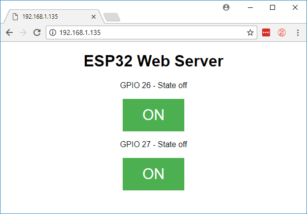
직렬 모니터를 살펴보면 백그라운드에서 무슨 일이 일어나고 있는지 볼 수 있습니다. ESP는 새 클라이언트(이 경우 브라우저)로부터 HTTP 요청을 받습니다.

HTTP 요청에 대한 다른 정보도 볼 수 있습니다.
웹 서버 테스트
이제 웹 서버가 제대로 작동하는지 테스트할 수 있습니다. 버튼을 클릭하여 LED를 제어합니다.

동시에, 직렬 모니터를 살펴보면 백그라운드에서 무슨 일이 일어나고 있는지 확인할 수 있습니다. 예를 들어, 버튼을 클릭하여 켜면GPIO 26 ON, ESP32는 /26/on URL 에서 요청을 수신합니다 .

ESP32가 해당 요청을 수신하면 연결된 LED가 켜집니다.GPIO 26 ON하고 웹 페이지의 상태를 업데이트합니다.

버튼GPIO 27비슷한 방식으로 작동합니다. 제대로 작동하는지 테스트합니다.
코드 작동 방식
이 섹션에서는 코드를 자세히 살펴보고 코드가 어떻게 작동하는지 살펴보겠습니다.
가장 먼저 해야 할 일은 WiFi 라이브러리를 포함시키는 것입니다.
#include <WiFi.h>
이전에 언급했듯이, 다음 줄의 큰따옴표 안에 ssid와 비밀번호를 삽입해야 합니다.
const char* ssid = "*********";
const char* password = "****************";
그런 다음 웹 서버를 포트 80으로 설정합니다.
WiFiServer server(80);
다음 줄은 HTTP 요청의 헤더를 저장하는 변수를 생성합니다.
String header;
다음으로, 출력의 현재 상태를 저장하기 위해 보조 변수를 만듭니다. 출력을 더 추가하고 상태를 저장하려면 더 많은 변수를 만들어야 합니다.
String output26State = "off";
String output27State = "off";
또한 각 출력에 GPIO를 할당해야 합니다. 여기서는 다음을 사용합니다.GPIO 26 그리고 GPIO 27, 다른 적합한 GPIO를 사용할 수 있습니다.
const int output26 = 26;
const int output27 = 27;
setup()
이제 들어가보죠설정(). 먼저, 디버깅 목적으로 115200의 통신 속도로 직렬 통신을 시작합니다.
Serial.begin(115200);
또한 GPIO를 OUTPUT으로 정의하고 LOW로 설정합니다.
// Initialize the output variables as outputs
pinMode(output26, OUTPUT);
pinMode(output27, OUTPUT);

// Set outputs to LOW
digitalWrite(output26, LOW);
digitalWrite(output27, LOW);
다음 줄은 Wi-Fi 연결을 시작합니다.WiFi.begin(ssid, password)연결이 성공적으로 완료될 때까지 기다린 후 직렬 모니터에 ESP IP 주소를 인쇄합니다.
// Initialize the output variables as outputs
pinMode(output26, OUTPUT);
pinMode(output27, OUTPUT);

// Set outputs to LOW
digitalWrite(output26, LOW);
digitalWrite(output27, LOW);
loop()
loop()에서 우리는 새로운 클라이언트가 웹 서버에 연결을 설정할 때 무슨 일이 일어나는지 프로그래밍합니다.
ESP32는 항상 다음 줄을 통해 들어오는 클라이언트를 수신합니다.
WiFiClient client = server.available(); // Listen for incoming clients
클라이언트로부터 요청을 받으면 들어오는 데이터를 저장합니다. 이어지는 while 루프는 클라이언트가 연결된 상태를 유지하는 한 계속 실행됩니다. 무엇을 하는지 정확히 알지 않는 한 코드의 다음 부분을 변경하지 않는 것이 좋습니다.
if (client) { // If a new client connects,
  Serial.println("New Client."); // print a message out in the serial port
  String currentLine = ""; // make a String to hold incoming data from the client
  while (client.connected()) { // loop while the client's connected
    if (client.available()) { // if there's bytes to read from the client,
      char c = client.read(); // read a byte, then
      Serial.write(c); // print it out the serial monitor
      header += c;
      if (c == '\n') { // if the byte is a newline character
      // if the current line is blank, you got two newline characters in a row.
      / that's the end of the client HTTP request, so send a response:
        if (currentLine.length() == 0) {
        // HTTP headers always start with a response code (e.g. HTTP/1.1 200 OK)
        // and a content-type so the client knows what's coming, then a blank line:
          client.println("HTTP/1.1 200 OK");
          client.println("Content-type:text/html");
          client.println("Connection: close");
          client.println();
if와 else 문의 다음 섹션은 웹 페이지에서 어떤 버튼이 눌렸는지 확인하고 그에 따라 출력을 제어합니다. 이전에 살펴본 것처럼, 우리는 눌린 버튼에 따라 다른 URL에 요청을 합니다.
// turns the GPIOs on and off
if (header.indexOf("GET /26/on") >= 0) {
  Serial.println("GPIO 26 on");
  output26State = "on";
  digitalWrite(output26, HIGH);
} else if (header.indexOf("GET /26/off") >= 0) {
  Serial.println("GPIO 26 off");
  output26State = "off";
  digitalWrite(output26, LOW);
} else if (header.indexOf("GET /27/on") >= 0) {
  Serial.println("GPIO 27 on");
  output27State = "on";
  digitalWrite(output27, HIGH);
} else if (header.indexOf("GET /27/off") >= 0) {
  Serial.println("GPIO 27 off");
  output27State = "off";
  digitalWrite(output27, LOW);
}
예를 들어, GPIO 26 ON 버튼을 눌렀다면 ESP32는 /26/ON URL 에서 요청을 수신합니다(Serial Monitor의 HTTP 헤더에서 해당 정보를 볼 수 있음). 따라서 헤더에 GET /26/on 표현식이 포함되어 있는지 확인할 수 있습니다 . 포함되어 있으면 다음을 변경합니다. output26state 변수를 ON으로 설정하면 ESP32가 LED를 켭니다.
다른 버튼에도 비슷하게 작동합니다. 따라서 출력을 더 추가하려면 코드의 이 부분을 수정하여 포함해야 합니다.
HTML 웹 페이지 표시
다음으로 해야 할 일은 웹 페이지를 만드는 것입니다. ESP32는 웹 페이지를 빌드하기 위한 HTML 코드와 함께 브라우저에 응답을 보냅니다.
웹 페이지는 이 표현을 사용하여 클라이언트에게 전송됩니다.클라이언트.println()클라이언트에게 보내고 싶은 내용을 인수로 입력해야 합니다.
우리가 가장 먼저 보내야 할 것은 항상 다음 줄입니다. 이는 우리가 HTML을 보낸다는 것을 나타냅니다.
<!DOCTYPE HTML><html>
그러면 다음 줄은 모든 웹 브라우저에서 웹 페이지가 반응형으로 표시되도록 만듭니다.
client.println("<head><meta name=\"viewport\" content=\"width=device-width, initial-scale=1\">");
그리고 다음은 favicon에 대한 요청을 방지하는 데 사용됩니다. – 이 줄은 걱정할 필요가 없습니다.
client.println("<link rel=\"icon\" href=\"data:,\">");
웹 페이지 스타일링
다음으로, 버튼과 웹 페이지 모양을 스타일링할 CSS 텍스트가 있습니다. Helvetica 글꼴을 선택하고, 블록으로 표시되고 중앙에 정렬될 콘텐츠를 정의합니다.
client.println("<style>html { font-family: Helvetica; display: inline-block; margin: 0px auto; text-align: center;}");
테두리 없는 #4CAF50 색상, 흰색 텍스트, 이 패딩으로 버튼 스타일을 지정했습니다: 16px 40px. 또한 텍스트 장식을 없음으로 설정하고 글꼴 크기, 여백, 커서를 포인터로 정의합니다.
client.println(".button { background-color: #4CAF50; border: none; color: white; padding: 16px 40px;");
client.println("text-decoration: none; font-size: 30px; margin: 2px; cursor: pointer;}");
또한 앞서 정의한 버튼의 모든 속성을 사용하지만 색상은 다른 두 번째 버튼의 스타일을 정의합니다. 이것이 꺼짐 버튼의 스타일이 됩니다.
client.println(".button2 {background-color: #555555;}</style></head>");
웹 페이지 첫 번째 제목 설정
다음 줄에서 웹 페이지의 첫 번째 제목을 설정할 수 있습니다. 여기에는 " ESP32 웹 서버 "가 있지만, 이 텍스트를 원하는 대로 변경할 수 있습니다.
// Web Page Heading
client.println("<h1>ESP32 Web Server</h1>");
버튼 및 해당 상태 표시하기
그런 다음, 표시할 문단을 작성합니다. GPIO 26현재 상태입니다. 보시다시피 우리는 다음을 사용합니다.출력26상태변수이므로 이 변수가 변경되면 상태가 즉시 업데이트됩니다.
client.println("<p>GPIO 26 - State " + output26State + "</p>");
그런 다음 GPIO의 현재 상태에 따라 켜기 또는 끄기 버튼을 표시합니다. GPIO의 현재 상태가 꺼져 있으면 켜기 버튼을 표시하고, 그렇지 않으면 끄기 버튼을 표시합니다.
if (output26State=="off") {
  client.println("<p><a href=\"/26/on\"><button class=\"button\">ON</button></a></p>");
} else {
  client.println("<p><a href=\"/26/off\"><button class=\"button button2\">OFF</button></a></p>");
}
우리는 동일한 절차를 사용합니다 GPIO 27.
연결 닫기
마지막으로 응답이 끝나면 우리는 다음을 지웁니다.헤더변수를 사용하고 클라이언트와의 연결을 중지합니다. client.stop().
// Clear the header variable
header = "";
// Close the connection
client.stop();
마무리하기
이 튜토리얼에서는 ESP32로 웹 서버를 만드는 방법을 보여드렸습니다. 두 개의 LED를 제어하는 간단한 예를 보여드렸지만, 아이디어는 해당 LED를 릴레이나 제어하려는 다른 출력으로 바꾸는 것입니다. ESP32를 사용한 다른 프로젝트는 다음 튜토리얼을 확인하세요.
'ESP32' 카테고리의 다른 글
| ESP32 SSD1306 OLED 디스플레이 (6) | 2024.10.17 |
|---|---|
| ESP32 BME280 압력, 온도, 습도 데이터 읽기 (0) | 2024.10.14 |
| ESP32 DHT11 DHT22 온도 및 습도 센서 모니터 회로와 코드 (0) | 2024.10.14 |
| ESP32 가전 제품을 제어하는 정전식 터치 센서 회로 (17) | 2024.10.13 |
| 아두이노 Nano ESP32 사용 가이드 4 치트 시트 (8) | 2024.10.11 |
| ESP32 개발 보드 시작하기 1 - Blink와 모든 정보 (17) | 2024.10.09 |
| ESP32 IoT 기반 기상 관측소 (3) | 2024.10.07 |
| Arduino Nano ESP32 Micro Python, IoT Cloud 가이드 (6) | 2024.10.07 |
취업, 창업의 막막함, 외주 관리, 제품 부재!
당신의 고민은 무엇입니까? 현실과 동떨어진 교육, 실패만 반복하는 외주 계약,
아이디어는 있지만 구현할 기술이 없는 막막함.
우리는 알고 있습니다. 문제의 원인은 '명확한 학습, 실전 경험과 신뢰할 수 있는 기술력의 부재'에서 시작됩니다.
이제 고민을 멈추고, 캐어랩을 만나세요!
코딩(펌웨어), 전자부품과 디지털 회로설계, PCB 설계 제작, 고객(시장/수출) 발굴과 마케팅 전략으로 당신을 지원합니다.
제품 설계의 고수는 성공이 만든 게 아니라 실패가 만듭니다. 아이디어를 양산 가능한 제품으로!
귀사의 제품을 만드세요. 교육과 개발 실적으로 신뢰할 수 있는 파트너를 확보하세요.
캐어랩


