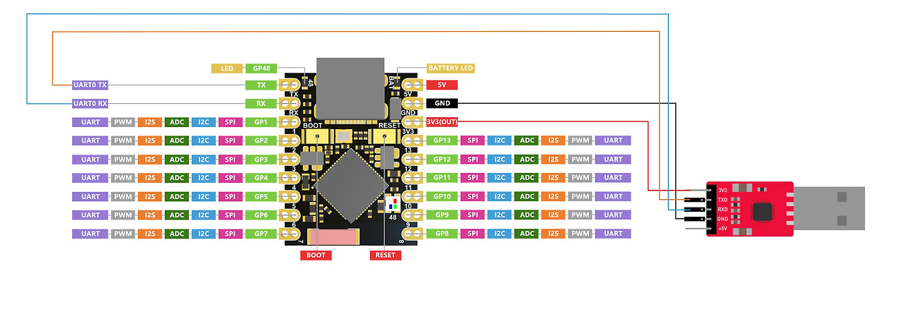
ESP32S3SuperMini는 다양한 인터페이스를 제공합니다. 11개의 디지털 I/O는 PWM 핀으로 사용 가능하며, 4개의 아날로그 입력은 ADC 핀으로 활용할 수 있습니다. UART, I2C, SPI 및 I2S 등 4가지 시리얼 통신 인터페이스를 지원합니다.
본 튜토리얼의 전체 포스팅 내용입니다.
ESP32S3 Super Mini 블루투스 ChatGPT 4
ESP32S3 Super Mini GPIO 핀 사용법 5
아두이노, 라즈베리파이b5, ESP32, OpenCV에 관한 빠르게 시작하기 기술 문서는 다음 링크에서 다운받으세요.
캐어랩 기술 문서 다운로드
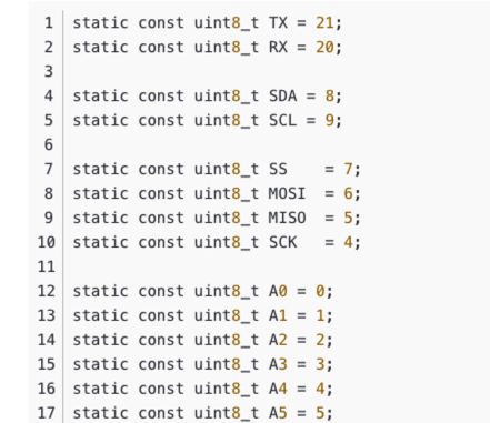
핀 A0~A5, GPIO0~GPIO10(0~10), 그리고 D로 시작하는 핀에 대해 설명합니다. 기본적으로 메인보드에는 GPIO로 시작하는 0, 10, 20, 21 핀만 있습니다. A0~A5 핀이 나타나는 것은 매핑 문제로, 사용자에게 해당 핀을 알리기 위한 편의상 처리입니다. Arduino의 유용한 정보는 다음과 같습니다. ESP32S3 Dev Module은 아래에 있습니다.

Digital 디지털 핀
아래 코드를 메인보드에 업로드하면, 보드에 장착된 LED가 1초마다 켜졌다 꺼집니다.
// define led according to pin diagram
int led = 8;

void setup() {
  // initialize digital pin led as an output
  pinMode(led, OUTPUT);
}

void loop() {
  digitalWrite(led, HIGH);   // turn the LED on
  delay(1000);               // wait for a second
  digitalWrite(led, LOW);    // turn the LED off
  delay(1000);               // wait for a second
}
디지털 PWM
아래 코드를 업로드하면 보드 내장 LED가 점차 어두워지는 것을 확인할 수 있습니다.
int ledPin = 8;    // LED connected to digital pin 10

void setup() {
  // declaring LED pin as output
  pinMode(ledPin, OUTPUT);
}

void loop() {
  // fade in from min to max in increments of 5 points:
  for (int fadeValue = 0 ; fadeValue <= 255; fadeValue += 5) {
    // sets the value (range from 0 to 255):
    analogWrite(ledPin, fadeValue);
    // wait for 30 milliseconds to see the dimming effect
    delay(30);
  }

  // fade out from max to min in increments of 5 points:
  for (int fadeValue = 255 ; fadeValue >= 0; fadeValue -= 5) {
    // sets the value (range from 0 to 255):
    analogWrite(ledPin, fadeValue);
    // wait for 30 milliseconds to see the dimming effect
    delay(30);
  }
}
아날로그 핀
포텐셔미터를 핀 A5에 연결한 후 아래 코드를 업로드하면, 포텐셔미터 노브를 돌리는 것으로 LED 깜빡임 간격을 제어할 수 있습니다.
const int sensorPin = A5;
const int ledPin =  8;

void setup() {
  pinMode(sensorPin, INPUT);  // declare the sensorPin as an INPUT
  pinMode(ledPin, OUTPUT);   // declare the ledPin as an OUTPUT
}

void loop() {
  // read the value from the sensor:
  int sensorValue = analogRead(sensorPin);
  // turn the ledPin on
  digitalWrite(ledPin, HIGH);
  // stop the program for <sensorValue> milliseconds:
  delay(sensorValue);
  // turn the ledPin off:
  digitalWrite(ledPin, LOW);
  // stop the program for for <sensorValue> milliseconds:
  delay(sensorValue);
}
Serial 시리얼 포트 하드웨어 시리얼 포트
보드에는 두 개의 하드웨어 시리얼 포트가 있습니다.
- USB 시리얼 포트
- UART 시리얼 포트
기본적으로 USB 시리얼은 활성화 상태입니다. 즉, USB Type-C를 통해 개발 보드를 PC에 연결하고 Arduino IDE에서 시리얼 모니터를 열어 시리얼로 전송되는 데이터를 확인할 수 있습니다.
그러나 UART를 시리얼 포트로서 사용하려면 USB 시리얼 어댑터를 사용하여 TX 핀을 TX 핀에, RX 핀을 RX 핀에 연결해야 합니다.

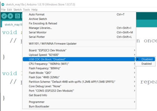
또한 Arduino IDE에서 USB CDC On Boot 설정을 비활성화해야 합니다.

소프트웨어 시리얼 포트
더 많은 시리얼 포트를 사용하려면 SoftwareSerial 라이브러리를 사용하여 소프트웨어 시리얼 포트를 생성해야 합니다. (직접 검색해 볼 수 있습니다)
튜토리얼 출처는 다음 링크를 따라가세요.
'ESP32' 카테고리의 다른 글
| ESP32C3 Ultra-Low Power SoCs 소개 1 (0) | 2025.09.30 |
|---|---|
| ESP32 WROOM32 GPIO 할당 테이블 양식 한글 파일 (0) | 2025.09.28 |
| ESP32-WROOM-32 핀아웃 참조 Pinout (0) | 2025.09.22 |
| esp32 충돌센서 방향 지시등 구현 (0) | 2025.09.19 |
| ESP32S3 Super Mini 블루투스 ChatGPT 4 (0) | 2025.09.15 |
| ESP32S3 Super Mini 블루투스 사용법 3 (0) | 2025.09.15 |
| ESP32S3 Super Mini WiFi 사용 2 (0) | 2025.09.15 |
| ESP32S3 Super Mini 시작하기 1 (0) | 2025.09.15 |
취업, 창업의 막막함, 외주 관리, 제품 부재!
당신의 고민은 무엇입니까? 현실과 동떨어진 교육, 실패만 반복하는 외주 계약,
아이디어는 있지만 구현할 기술이 없는 막막함.
우리는 알고 있습니다. 문제의 원인은 '명확한 학습, 실전 경험과 신뢰할 수 있는 기술력의 부재'에서 시작됩니다.
이제 고민을 멈추고, 캐어랩을 만나세요!
코딩(펌웨어), 전자부품과 디지털 회로설계, PCB 설계 제작, 고객(시장/수출) 발굴과 마케팅 전략으로 당신을 지원합니다.
제품 설계의 고수는 성공이 만든 게 아니라 실패가 만듭니다. 아이디어를 양산 가능한 제품으로!
귀사의 제품을 만드세요. 교육과 개발 실적으로 신뢰할 수 있는 파트너를 확보하세요.
캐어랩


