이전 글에서 FreeRTOS에서 동시에 실행되는 여러 작업을 생성하는 방법을 배웠습니다. 또한 작업에 사용되는 변수에 초기값을 전달하고 전역 변수와 구조체를 사용하여 작업 간에 정보를 교환하는 방법도 배웠습니다. FreeRTOS의 제어 하에 동시에 실행되는 6개의 작업으로 구성된 시스템을 구축했습니다. 3과에서는 작업이 제어된 순서대로 실행되도록 동기화하는 몇 가지 기술을 배우게 됩니다. 이 기술이 중요한 데에는 몇 가지 이유가 있습니다.
- 많은 응용 프로그램에서는 정보가 명확하게 정의되고 일관된 순서로 수집되고 처리되어야 한다는 엄격한 요구 사항이 있습니다.
- 작업 출력이 서로 겹치지 않도록 인쇄 서비스와 같은 공유 리소스에 대한 액세스를 제어해야 하는 경우가 많습니다.
- 일부 작업은 외부 이벤트에 반응하여 인터럽트나 타이머에 의해 트리거되어야 합니다.
본 학습자료의 전체 구성은 아래와 같습니다.
Arduino를 사용하여 ESP32 보드에 FreeRTOS 구현하기 개요
Arduino를 사용하여 ESP32 보드에 FreeRTOS 구현하기 1
Arduino를 사용하여 ESP32 보드에 FreeRTOS 구현하기 2
Arduino를 사용하여 ESP32 보드에 FreeRTOS 구현하기 3
Arduino를 사용하여 ESP32 보드에 FreeRTOS 구현하기 4
이를 위해 실시간 운영 체제에서 처리 순서를 제어하는 데 사용되는 매우 일반적인 네 가지 방법을 살펴보겠습니다.
- 인터럽트 및 타이머 이벤트
- 세마포어 Semaphore
- 뮤텍스 Mutex
- 대기열 Queus
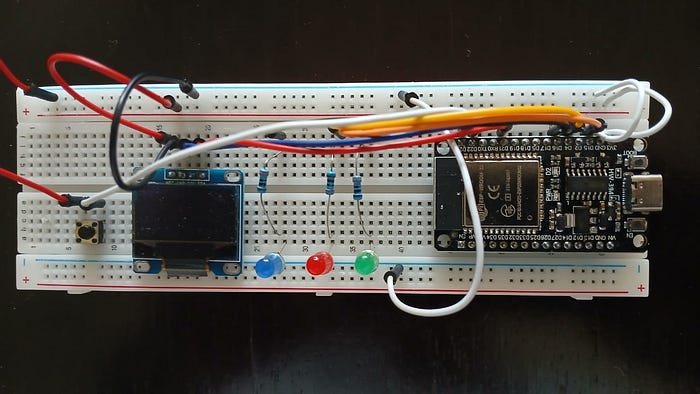
이전 레슨과 동일한 하드웨어를 사용하고 레슨 2에서 개발한 소프트웨어를 기반으로 구축할 것입니다. 주의: 이번 레슨은 다른 레슨보다 조금 더 길었지만, 네 가지 동기화 주제를 모두 함께 살펴보는 것이 유용하다고 생각했습니다. 더 많은 코드가 필요하지만, 대부분은 매우 일반적인 Arduino 코드입니다. 여러분이 집중할 수 있도록 FreeRTOS 전용 코드를 강조하려고 노력했습니다.
인터럽트 및 타이머 이벤트
외부 트리거 이벤트나 특정 시간 경과에 따라서만 실행되어야 하는 작업이 있는 경우가 많습니다. 2과에서는 버튼 누름으로 트리거되는 인터럽트를 사용하여 속도 향상 작업을 호출하고 LED 깜박임 속도를 변경했습니다. 이 연습에서는 타이머에서 생성된 인터럽트를 추가하여 직렬 콘솔에 하이워터 마크 출력을 호출합니다. 이전 코드는 각 작업의 메모리 사용량 스냅샷을 제공하기 위해 실행 시작 후 5초 후에 한 번씩 작업을 실행했습니다. 이제 10초마다 실행되도록 수정하여 시간 경과에 따라 메모리 요구량이 변하는지 확인할 것입니다. FreeRTOS 함수 xTimerCreate를 사용하여 예약된 시간에 따라 콜백 함수를 반복적으로 시작하는 타이머를 설정하고, 콜백에서 하이워터 마크 작업을 다시 시작합니다. 시작하려면 2과에서 완성한 스케치를 다시 로드하고 rtosLesson3이라는 이름으로 저장합니다. 필요한 변경 사항은 아래와 같습니다.
// 8 - define function for highwater mark
UBaseType_t uxTaskGetStackHighWaterMark(TaskHandle_t xTask);
TimerHandle_t highwaterTimer; // define data types for the highwater mark timer
BaseType_t hwTimerStarted;
먼저, 타이머 함수에서 사용하는 데이터 유형을 정의하기 위해 섹션 8에 두 줄을 추가합니다.
// setup button for interupt processing
  pinMode(pinButton, INPUT_PULLUP);
  attachInterrupt(pinButton, buttonPush, FALLING);

  highwaterTimer = xTimerCreate("Highwater Timer",pdMS_TO_TICKS(10000),pdTRUE,0,hwCallback);
  hwTimerStarted = xTimerStart( highwaterTimer, 0 );
다음으로, 코드의 설정 섹션에 highwaterTimer를 생성하고 시작하는 코드를 추가합니다. xTimerCreate 함수에 전달되는 인수는 다음과 같습니다.
- 타이머에 대한 설명적 이름(텍스트)
- 타이머 이벤트 사이의 틱 수(10000밀리초)
- 반복 표시기(pdFALSE로 설정하면 한 번만 트리거됨)
- 타이머 ID(여기서는 사용되지 않음)
- 타이머 이벤트가 발생할 때 실행할 콜백 함수의 이름
xTimerStart 함수는 타이머 핸들 이름과 타이머 큐가 사용 가능할 때까지 대기할 시간을 인수로 받습니다. 다음으로, 앞서 생성한 TaskHighwaterMark 함수의 시작 부분 근처에 있는 vTaskDelay 함수를 주석 처리하여 약간 수정합니다. 타이머 콜백을 사용하여 함수를 시작합니다.
void TaskHighWater(void *pvParameters)
{
  while (true) //run forever
  {
    //vTaskDelay(pdMS_TO_TICKS(5000));   // wait 5 seconds so system is fully running
    // display highwater marks for all 6 tasks
    Serial.println("***************************");
    Serial.print("High Water Mark for Green LED : ");
    Serial.println(uxTaskGetStackHighWaterMark(taskGreen));
    Serial.print("High Water Mark for Red LED : ");
    Serial.println(uxTaskGetStackHighWaterMark(taskRed));
    Serial.print("High Water Mark for Blue LED : ");
    Serial.println(uxTaskGetStackHighWaterMark(taskBlue));
    Serial.print("High Water Mark for Tally : ");
    Serial.println(uxTaskGetStackHighWaterMark(taskTally));
    Serial.print("High Water Mark for Highwater Task: ");
    Serial.println(uxTaskGetStackHighWaterMark(taskHighwater));
    Serial.print("High Water Mark for Speed: ");
    Serial.println(uxTaskGetStackHighWaterMark(taskSpeed));
    Serial.flush(); // make sure last data is written

    vTaskSuspend(NULL); // run this task only once
  }
}
마지막으로 타이머 콜백 함수를 추가할 수 있습니다. 파일 하단에 다음 줄을 추가하세요.
void hwCallback( TimerHandle_t xTimer )
{
vTaskResume(taskHighwater); // run the highwater program once
}
이제 코드를 회로에 다운로드하고 시리얼 콘솔을 여세요. 이제 시리얼 콘솔에 10초마다 최고값 데이터가 업데이트되는 것을 볼 수 있을 것입니다.
세마포어
세마포어는 작업 간 실행 흐름을 동기화하고 제어하는 데 도움이 되는 특수 프로그래밍 도구입니다. 비유하자면, 각 팀에서 한 명씩 주자가 달리고 경주가 진행됨에 따라 한 주자에서 다음 주자에게 바통이 전달되는 릴레이 경주를 생각해 보세요. 릴레이 경주에서 바통을 전달하는 것과 유사한 방식으로 세마포어를 사용하여 FreeRTOS 작업의 실행 순서를 제어할 수 있습니다. 가장 간단한 형태는 사용 가능(available)과 사용됨(taked)의 두 가지 상태를 갖는 이진 세마포어입니다. 세마포어를 사용하면 한 작업에 다른 작업보다 우선순위를 부여하고 다른 작업들이 세마포어를 요청하여 실행을 계속하기 전에 세마포어가 해제될 때까지 기다리도록 할 수 있습니다. 카운팅 세마포어는 여러 작업이 특정 한계(카운트)까지 동일한 세마포어를 동시에 획득할 수 있도록 합니다. 그 후에는 다른 작업들이 운영 중인 작업 중 하나가 세마포어를 반환할 때까지 기다려야 합니다. 이는 동시에 작업을 수행할 수 있는 작업 수를 제한하려는 경우 매우 유용합니다. 이 연습에서는 바이너리 세마포어를 사용하여 세 개의 LED 표시등이 순차적으로 깜박이도록 동기화합니다. rtosLesson3 스케치를 다시 열어 코드를 수정해 보겠습니다.
//define semaphore object handle
SemaphoreHandle_t syncFlag;

// 6 - load up data for each LED task
static BlinkData blinkGreen = { 15, 2000, &speedMult, &greenLED };
static BlinkData blinkRed = { 4, 2000, &speedMult, &redLED };
static BlinkData blinkBlue = { 16, 2000, &speedMult, &blueLED };
먼저 초기화 코드 섹션에서 syncFlag라는 세마포어 핸들을 정의한 다음, 각 LED의 지연 시간이 동일하도록 각 LED의 데이터를 업데이트합니다.
// initialize serial communication at 115200 bits per second:
  Serial.begin(115200);

// create the binary semaphore
  syncFlag = xSemaphoreCreateBinary();
  if (syncFlag != NULL){Serial.println("flag OK");}
다음 단계는 syncFlag라는 바이너리 세마포어를 생성하는 것입니다. 시리얼 콘솔을 시작한 직후 설정 섹션에 이 세마포어를 추가합니다. 성공적으로 생성되었는지 확인하고 결과 메시지를 출력합니다. 이 시점에서 플래그는 초기화되었지만 아직 사용할 수 없습니다.
// Now set up tasks to run independently.
  xTaskCreatePinnedToCore
    (
    TaskBlinkSeq, // name of function to invoke
    "TaskBlinkGreen" , // label for the task
    4096 , // This stack size can be checked & adjusted by reading the Stack Highwater
    (void *)&blinkGreen, // pointer to global data area
    3 , // Priority,
    &taskGreen, //pointer to task handle
    ARDUINO_RUNNING_CORE // run on the arduino process core
    );

  xTaskCreatePinnedToCore
    (
    TaskBlinkSeq,
    "TaskBlinkRed",
    4096,
    (void *)&blinkRed,
    3,
    &taskRed,
    ARDUINO_RUNNING_CORE
    );

  xTaskCreatePinnedToCore
    (
    TaskBlinkSeq,
    "TaskBlinkBlue",
    4096,
    (void *)&blinkBlue,
    3,
    &taskBlue,
    ARDUINO_RUNNING_CORE
    );
다음으로, TaskBlinkSeq라는 새로운 작업 함수를 사용하도록 작업 생성 명령을 수정합니다. 또한 각 작업에 우선순위를 3으로 지정합니다.
// make the syncFlag semaphore available to start sequential processing
xSemaphoreGive(syncFlag);

} //end of setup
설정 섹션의 마지막에 xSemaphoreGive 함수를 추가하여 스케줄러가 시작되자마자 세마포어를 사용할 수 있도록 합니다.
void TaskBlinkSeq(void *xStruct)  // This is a task template
{
  BlinkData *data = (BlinkData *)xStruct; //passed data cast as BlinkData structure
  // unpack data from the BlinkData structure passed by reference
  int pin = data->pin;
  int delay = data->delay;
  float *speedMult = data->speedMult;
  int *statePtr = data->ptr;


  // set pinMode on output pin
  pinMode(pin, OUTPUT);

  while(true)  // A Task shall never return or exit.
  {
    // get the semaphores
    xSemaphoreTake(syncFlag, 5000 );
    int delayInt = (delay * (*speedMult)); // get nearest int to new delay time

    digitalWrite(pin, HIGH);           // turn the LED on (HIGH is the voltage level)
    *statePtr = 1;                     // set the LED state to 1
      // unblock delay for on cycle time
    vTaskDelay(pdMS_TO_TICKS(delayInt));
    digitalWrite(pin, LOW);            // turn the LED off by making the voltage LOW
    *statePtr = 0;
    xSemaphoreGive(syncFlag);
    vTaskDelay(pdMS_TO_TICKS(100));
    }
}
다음은 새 코드의 핵심인 TaskBlinkSeq 함수입니다. 각 호출에서 세마포어를 가져와 LED를 켜고, 지연 시간 동안 기다린 후 LED를 끄고 세마포어를 해제합니다. 실행 흐름을 요약하면 다음과 같습니다.
- BlinkData 구조체에서 전달된 데이터를 압축 해제합니다.
- 현재 핀의 핀 모드를 설정하여 값을 변경할 수 있습니다.
- xSemaphoreTake 함수를 사용하여 세마포어가 사용 가능할 때 가져옵니다. 세마포어가 사용 가능할 때까지 최대 5000틱 동안 기다린 후 나머지 작업을 중단하고 작업을 중단합니다.
- LED를 켜고 상태 포인터를 업데이트합니다.
- 기본 지연과 속도 배수에 따라 일정 시간 동안 기다립니다.
- LED를 끄고 해당 상태 포인터를 업데이트합니다.
- xSemaphoreGive 함수를 사용하여 플래그를 해제하고 다음 작업에서 해당 플래그를 사용하게 합니다.
- 세마포어를 획득하기 위해 루프백하기 전에 잠시 기다립니다. 이렇게 하면 시간 분할 중간에 세마포어 해제가 발생하더라도 태스크가 순서를 어기고 세마포어를 다시 획득하는 것을 방지할 수 있습니다.
시스템은 조명 순서를 어떻게 알 수 있을까요? 세 개의 LED 작업에 다른 작업보다 높은 우선순위(3)를 부여했으므로, 스케줄러는 세 작업에 우선순위를 먼저 부여하고 라운드 로븐 방식으로 처리하여 순차적으로 차례대로 실행되도록 합니다.
void TaskTally(void *pvParameters)  // This is a task template
{
  (void)pvParameters;

  TickType_t xLastWaitTime;  //updated after first call by vTaskDelaUntil

  // initialize xLastWaitTime
  xLastWaitTime = xTaskGetTickCount();

  // initialize the lcd display (once)
  Adafruit_SSD1306 Display(OLED_RESET);
  Display.begin(SSD1306_SWITCHCAPVCC, OLED_ADDR);
  Display.clearDisplay();
  Display.display();

  while (true)  // A Task shall never return or exit.
  {
    // calcualte numer of lamps lit from global variables
    //int numLit = redLED + greenLED + blueLED;
    // determine LED color
    char colorStr[6] ;
    if (redLED == 1){strcpy(colorStr,"Red");}
    else if (greenLED == 1){strcpy(colorStr,"Green");}
    else if (blueLED == 1){strcpy(colorStr,"Blue ");}
    else {strcpy(colorStr,"");}
    //display data on LCD display
    Display.clearDisplay();
    Display.setTextSize(1);
    Display.setTextColor(WHITE);
    Display.setCursor(40, 0);
    Display.println("LED Lit");
    Display.setTextSize(2);
    Display.setTextColor(WHITE);
    Display.setCursor(60, 15);
    Display.println(colorStr);
    //Display.println(String(numLit));
    Display.display();
    // short unblocked delay between readings (1/10 second)
    xTaskDelayUntil(&xLastWaitTime, pdMS_TO_TICKS(100));
  }
마지막으로 TaskTally 함수의 코드를 수정합니다. LED가 순차적으로 켜지면 항상 1개이므로 켜진 LED의 개수를 기록하는 것은 의미가 없습니다. 대신 OLED에 현재 켜져 있는 LED의 색상을 표시하도록 하겠습니다. 변경 사항은 위에 나와 있습니다.
이제 새로운 프로그램을 컴파일하고 업로드하면 회로가 이렇게 작동하는 것을 볼 수 있습니다.
뮤텍스
다음으로, 시리얼 콘솔에 입력된 명령을 입력하고 응답하는 기능을 추가하겠습니다. 이렇게 하면 더 많은 버튼을 누르지 않고도 장치와 상호 작용할 수 있지만, 잠재적인 문제가 발생합니다. 명령 프로세서가 데이터를 쓰는 동시에 하이워터 이벤트가 콘솔에 데이터를 표시하기로 결정하면 어떻게 될까요? 적절한 제어가 없다면 엉망이 될 것입니다. 하지만 이러한 상황을 해결하기 위해 특별히 고안된 뮤텍스라는 세마포어의 특별한 변형이 있습니다. 뮤텍스는 "상호 배타적(mutually exclusive)"의 약자로, 작업이 일정 기간 동안 공유 리소스에 대한 배타적 접근을 예약할 수 있도록 하는 데 사용됩니다. 작업이 더 이상 리소스에 대한 배타적 접근을 필요로 하지 않으면, 다른 작업이 해당 리소스를 사용할 수 있도록 뮤텍스를 해제할 수 있습니다(실제로는 반드시 해제해야 합니다). 콘솔 명령을 읽고 처리하는 코드를 작성하기 전에 뮤텍스를 추가하고 이전에 작성된 하이워터 마크 작업에 적용합니다.
// the setup function runs once when you press reset or power the board
void setup() {

  // initialize serial communication at 115200 bits per second:
  Serial.begin(115200);

  // create the binary semaphore
  syncFlag = xSemaphoreCreateBinary();
  if (syncFlag != NULL){Serial.println("flag OK");}

  // start printer mutex access
  SemaphoreHandle_t printMutex;
  printMutex = xSemaphoreCreateMutex();
  if (printMutex != NULL){Serial.println("printMutex created");}
설정 섹션에서는 바이너리 세마포어 아래에 printMutex라는 프린터 액세스 뮤텍스를 설정하는 새 섹션을 추가했습니다. 이제 TaskHighWater 함수 시작 부분에서 printMutex 세마포어를 가져오고, 함수 끝 부분에서 반환하는 호출을 아래와 같이 추가합니다.
void TaskHighWater(void *pvParameters)
{
  while (true) //run forever
  {
    //vTaskDelay(pdMS_TO_TICKS(5000));   // wait 5 seconds so system is fully running
    // display highwater marks for all 6 tasks
    xSemaphoreTake(printMutex,portMAX_DELAY);  // get the printer mutex for use of the printer
    Serial.println("***************************");
    Serial.print("High Water Mark for Green LED : ");
    Serial.println(uxTaskGetStackHighWaterMark(taskGreen));
    Serial.print("High Water Mark for Red LED : ");
    Serial.println(uxTaskGetStackHighWaterMark(taskRed));
    Serial.print("High Water Mark for Blue LED : ");
    Serial.println(uxTaskGetStackHighWaterMark(taskBlue));
    Serial.print("High Water Mark for Tally : ");
    Serial.println(uxTaskGetStackHighWaterMark(taskTally));
    Serial.print("High Water Mark for Highwater Task: ");
    Serial.println(uxTaskGetStackHighWaterMark(taskHighwater));
    Serial.print("High Water Mark for Speed: ");
    Serial.println(uxTaskGetStackHighWaterMark(taskSpeed));
    Serial.flush(); // make sure last data is written
    xSemaphoreGive(printMutex); //release the printer mutex
    vTaskSuspend(NULL); // run this task only once
  }
}
뮤텍스 세마포어와 일반 바이너리 세마포어의 차이점은 무엇일까요? 뮤텍스는 상호 배타적이므로, 뮤텍스를 해제할 수 있는 작업은 뮤텍스를 획득한 작업뿐입니다. 따라서 뮤텍스를 보유한 작업이 실패하거나, 일시 중단되거나, 장시간 차단되지 않도록 코드에 세심한 주의를 기울여야 합니다. 뮤텍스에 접근해야 하는 다른 작업에 문제를 일으킬 수 있기 때문입니다. 리소스 공유를 제어하는 더 정교한 방법도 있지만, 이 튜토리얼에서는 다루지 않습니다.
대기열 Queue
이제 명령 프로세서를 추가할 준비가 되었습니다. 두 부분으로 나누어 추가하겠습니다.
- 키보드 입력을 읽고 올바른 명령인지 확인하는 명령 파서입니다.
- 검증된 키보드 입력 항목을 가져와 요청된 명령을 수행하는 명령 실행기입니다.
검증된 명령을 명령 파서에서 명령 실행기로 전달하기 위해 대기열을 사용할 것입니다. 두 작업을 분리하는 이유는 무엇일까요? 향후 터치스크린 디스플레이, 웹 인터페이스 또는 다른 입력 방식을 통해 명령을 입력할 수 있는 기능을 추가할 수도 있습니다. 새로운 입력 장치가 명령 파서와 동일한 명령 대기열로 명령을 전송하도록 하면 추가 처리 코드를 작성할 필요가 없습니다. 시스템은 여러 소스의 입력을 일관된 방식과 올바른 순서로 처리할 수 있게 됩니다.
// 4 - define global variable for led status
int greenLED = 0;  // LED status indicator 0-off, 1-on
int redLED = 0;
int blueLED = 0;
int *greenPtr = &greenLED;  //pointers to pass to tasks to update led status
int *redPtr = &redLED;
int *bluePtr = &blueLED;
float speedMult = 1.0; // define speed multipier value

// define structure for data in the cmdQueue
const byte numChars = 24;
struct cmdData {
  char  Cmd[numChars];
  char  Obj[numChars];
};
// define the queue handle for the queCmd queue
QueueHandle_t queCmd;
먼저 초기화 코드에 명령 데이터를 저장할 전역 변수와 cmdData라는 구조체를 생성하는 섹션을 추가합니다. 또한 queCmd 큐에 대한 핸들을 정의합니다.
// the setup function runs once when you press reset or power the board
void setup() {

  // initialize serial communication at 115200 bits per second:
  Serial.begin(115200);

  // create the binary semaphore
  syncFlag = xSemaphoreCreateBinary();
  if (syncFlag != NULL){Serial.println("flag OK");}

  // start printer mutex access
  SemaphoreHandle_t printMutex;
  printMutex = xSemaphoreCreateMutex();
  if (printMutex != NULL){Serial.println("printMutex created");}

  // initialize queue for commands
  queCmd = xQueueCreate( 5, sizeof( cmdData ) );
  if( queCmd != NULL ) {Serial.println("command queue created");}
그런 다음 설정 섹션에서 명령 대기열을 생성하는 코드를 추가합니다. FreeRTOS 함수 xQueueCreate를 사용하여 queCmd라는 대기열을 생성합니다. 이 대기열에는 5개의 항목이 저장되며, 각 항목은 cmdData 구조체의 크기입니다. 명령 파서는 대기열의 뒤쪽에 값을 입력하고 명령 실행기는 앞쪽에서 항목을 읽어 명령이 입력된 순서대로 처리되도록 합니다. 처리할 명령은 빠르게 실행되므로 대기열 항목 수 제한인 5개를 초과할 염려가 없습니다.
명령 구조에 대해 살펴보겠습니다. 이 간단한 튜토리얼에서는 모든 명령이 명령 이름(Cmd 변수)과 객체 필드(Obj 변수)의 두 부분으로 구성됩니다. 명령 필드와 객체 필드에 허용되는 값은 다음과 같습니다.
- 일시 정지(빨간색, 녹색, 파란색)
- 이력서 (빨간색, 초록색, 파란색)
- (빨강, 초록, 파랑)을 죽이다
- 속도 (느리게, 빠르게)
즉, 각 LED 색상과 관련된 작업을 일시 중지, 재개 또는 종료하고 속도를 느리게 또는 빠르게 변경할 수 있습니다. 명령 파서는 키보드 입력이 위 값 중 하나와 일치하는지 확인한 후, cmdData 구조체의 내용을 가리키는 항목을 queCmd 대기열에 추가합니다. 한 가지 중요한 점은 대기열에 항목이 입력될 당시 cmdData 구조체 내용의 사본이 존재한다는 것입니다. 그러면 명령 파서는 대기열 내용에 영향을 주지 않고 새로운 항목 데이터를 수신할 수 있습니다.
// define  global variables for keyboard entry
char receivedChars[numChars];
char tempChars[numChars];        // temporary array for use when parsing
cmdData valueToSend;

// define global variables to hold the parsed input data
char cmdFromPC[numChars] = {0};
char objFromPC[numChars] = {0};
const char* cmdList = "kill...pause...resume...speed"; // list of accepted values for command
const char* objListLED = "red...green...blue";   // list of accepted values
const char* objListSpeed = "faster...slower";
boolean newData = false;

// the setup function runs once when you press reset or power the board
void setup() {
먼저 명령 구문 분석 루틴에 사용되는 전역 변수를 정의해야 합니다. 위 코드를 초기화 코드 끝부분, 즉 setup 함수 바로 앞에 삽입하세요.
void TaskCmdParse(void *pvParameters)  // This is a task template
{
  // This uses non-blocking input routines to read and check user input
  // If values are acceptable the command is sent to the command processor
  // The input format is "command object" where command and object must conform
  // to values in lists.  If either is not valid the user is notified.

  // define sub functions used here
  (void)pvParameters;
  void parseData(void);
  void checkParsedData(void);
  void recvWithEndMarker(void);


  while (true)  // A Task shall never return or exit.
  {
    BaseType_t xStatus; // *** 1 *** typedef statement

    recvWithEndMarker();
    if (newData == true) {
      strcpy(tempChars, receivedChars);
      strcat (tempChars, " 1 2 3"); //add spaces in case user didn't enter any
        // this temporary copy is necessary to protect the original data
        //   because strtok() used in parseData() replaces the commas with \0
      parseData();
      checkParsedData();
      newData = false;

      // load values into the struct used to send message in queue and send
      strcpy(valueToSend.Cmd, cmdFromPC);
      strcpy(valueToSend.Obj, objFromPC);

      // *** 2 *** add the input values to the back of the queue
      xStatus = xQueueSendToBack( queCmd, &valueToSend, 0 );
        if( xStatus != pdPASS ) {Serial.println("queue send failed!");}
    }
  }
}

  void parseData()       // split the data into its parts
    {

      char * strtokIndx; // this is used by strtok() as an index

      strtokIndx = strtok(tempChars," ");      // get the first part - the string
      strcpy(cmdFromPC, strtokIndx); // copy it to cmdFromPC

      strtokIndx = strtok(NULL, " "); // this continues where the previous call left off
      strcpy(objFromPC,strtokIndx);  // copy it to objFromPC
    }

  void checkParsedData()
    {
      // *** 3 *** take the printer mutex
      xSemaphoreTake(printMutex,portMAX_DELAY);
      char * cmd;
      char * obj;
      int validRequest = 0;
    cmd = strstr(cmdList,cmdFromPC);
      if (cmd){
        validRequest += 1;}
      else{
        Serial.println("rejected - unrecognized command");
        validRequest  -= 1;
      }
      if (strstr("speed",cmdFromPC))
        {
        obj = strstr(objListSpeed,objFromPC);
        if (obj)
          {
          validRequest  += 1;
          }
        else
          {
          Serial.println("rejected - unrecognized request");
          validRequest -= 1;
          }
        }
      else
        {
        obj = strstr(objListLED,objFromPC);
        if (obj)
          {
          validRequest  += 1;
          }
        else
          {
          Serial.println("rejected - unrecognized request");
          validRequest -= 1;
          }
        }
      if (validRequest == 2){
        Serial.println("command accepted");
        Serial.println(String(cmdFromPC) + "  " + String(objFromPC));
      }
    Serial.flush();
    // *** 4 *** flush the print data and wait three seconds for the user to read the response
    vTaskDelay(pdMS_TO_TICKS(5000));
    xSemaphoreGive(printMutex);
    }

  void recvWithEndMarker()
    {
      static byte ndx = 0;
      char endMarker = '\n';
      char rc;

      while (Serial.available() > 0 && newData == false) {
        rc = Serial.read();

        if (rc != endMarker) {
          receivedChars[ndx] = rc;
          ndx++;
          if (ndx >= numChars) {
              ndx = numChars - 1;
          }
        }
        else {
          receivedChars[ndx] = '\0'; // terminate the string
          ndx = 0;
          newData = true;
        }
      }
    }
다음으로 키보드 입력을 읽고, 파싱하고, 검증하고, 처리를 위해 queCmd 큐에 입력하는 코드를 삽입합니다. 이 긴 코드의 대부분은 표준 아두이노 코드와 문자 함수를 사용하여 데이터를 입력하고 확인하는 작업을 다루므로 자세히 설명할 필요는 없지만, print 뮤텍스와 명령 큐와 관련된 몇 가지 단계가 있습니다.
1 — 아래에 참조된 큐 항목 함수의 반환을 위한 typedef 문입니다.
2 — xQueueSendToBack FreeRTOS 함수를 사용하여 구문 분석 및 검증된 입력을 queCmd 대기열의 맨 뒤에 삽입합니다 . 이미 존재하는 다른 항목보다 먼저 대기열의 맨 앞으로 요청을 보내려면 xQueueSendToFront 함수를 사용할 수도 있습니다 .
3 — checkParsedData 함수는 키보드 입력을 검증한 후 명령이 수락되었는지 여부를 콘솔에 출력합니다. 코드의 3번 위치에서 printMutex를 사용하여 콘솔 출력을 독점적으로 사용할 수 있습니다.
4 — checkParsedData 함수가 끝나면 콘솔 출력을 해제할 준비가 됩니다. 하지만 먼저 프린터를 플러시하여 버퍼링된 모든 데이터가 출력되었는지 확인한 후, 다른 작업이 제어권을 갖기 전에 사용자가 출력을 읽을 수 있도록 5초간 기다립니다.
Arduino IDE는 디스플레이에 별도의 입력 필드를 가지고 있고 키 입력 처리 작업이 하나뿐이기 때문에 콘솔에 키 입력을 입력할 때 printMutex를 사용할 필요가 없습니다.
이제 이전과 마찬가지로 xTaskCreatePinned To Core FreeRTOS 함수를 사용하여 새 TaskCmdParse 함수를 활성화하기만 하면 됩니다. 아래 코드를 TaskHighWater 시작 코드 바로 아래에 삽입합니다.
// insert after TaskCreatePinnedToCore section for TaskHighWater
xTaskCreatePinnedToCore(
    TaskCmdParse,
    "Command Parser", // A name just for human
    4096,  // This stack size can be checked & adjusted by reading the Stack Highwater
    NULL,
    2,  // Priority
    &taskCmdParse,
    SYSTEM_RUNNING_CORE);  //run this in core separate from LED tasks if there are two cores
이제 아래와 같이 초기화 섹션에 핸들 정의를 추가합니다.
// 7 - set up task handles for the RTOS tasks
TaskHandle_t taskGreen;
TaskHandle_t taskRed;
TaskHandle_t taskBlue;
TaskHandle_t taskSpeed;
TaskHandle_t taskTally;
TaskHandle_t taskHighwater;
TaskHandle_t taskCmdParse; // add handle for the command parser
이제 queCmd 큐에서 명령을 읽고 요청을 처리하는 TaskCmdExec 라는 작업을 추가하기만 하면 됩니다 . 코드는 다음과 같습니다.
void TaskCmdExec(void *pvParameters)
{
(void)pvParameters;
cmdData receivedValue;
BaseType_t xStatus;
const TickType_t xTicksToWait = pdMS_TO_TICKS( 100 );
char nameObj[8];

  while (true)
  {
    // 5 - receive items from the queCmd queue
    // if new items are received xStatus is pdPass
    xStatus = xQueueReceive( queCmd, &receivedValue, xTicksToWait );
    if( xStatus == pdPASS ) // process new commands
      {
      // 6 - reserve the printer to respond to user
      xSemaphoreTake(printMutex,portMAX_DELAY);  // get the printer mutex for use of the printer

      // 7 - process the command request and print outcome
      if (strstr("red",receivedValue.Obj))
        {
        strcpy(nameObj,"red");
        taskCmd = taskRed;
        }
      else if (strstr("green",receivedValue.Obj))
        {strcpy(nameObj,"green");
        taskCmd = taskGreen;}
      else if (strstr("blue",receivedValue.Obj))
        {strcpy(nameObj,"blue");
        taskCmd = taskBlue;}

      // check which command is sent and respond accordingly
      if (strstr("pause",receivedValue.Cmd))
        {
        vTaskSuspend(taskCmd);
        Serial.print(nameObj);
        Serial.println(" paused");
        }
      else if (strstr("resume",receivedValue.Cmd))
        {
          vTaskResume(taskCmd);
          Serial.print(nameObj);
          Serial.println(" resumed");
        }
      else if (strstr("kill",receivedValue.Cmd))
              {
                vTaskDelete(taskCmd);
                Serial.print(nameObj);
                Serial.println(" killed");
        }
      else if (strstr("speed" , receivedValue.Cmd) )
        {
          if (strstr ( "slower" , receivedValue.Obj))
            {speedMult *= 1.5;
            Serial.println("speed is slower");}
          else if (strstr("faster" , receivedValue.Obj))
            {speedMult *= 0.67;
            Serial.println("speed is faster");}
        }
      // 8 - close out the printer and give back to print mutex
      Serial.flush();
      vTaskDelay(pdMS_TO_TICKS(5000)); // pause for the user to read
      xSemaphoreGive(printMutex); // flush the print buffer and release the print mutex
    }
    else
      {
      /* Do nothing here - Wait for a new entry to be added into the command queue */
      }
    }
  }
이 코드에서는 다음을 수행합니다.
5 — xQueueReceive FreeRTOS 함수를 사용하여 큐에 새 레코드가 나타나는지 확인합니다. 반환 값이 pdPass이면 처리할 새 데이터가 있으며 큐의 첫 번째 레코드 내용이 receivedValue 구조체에 저장됨을 의미합니다.
6 — 처리할 명령이 있는 경우 프린터 뮤텍스를 예약합니다.
7 — 요청된 명령을 처리합니다. 명령 구문 분석기가 이미 처리했기 때문에 구문을 확인할 필요가 없습니다.
8 — 인쇄 버퍼를 플러시하고 5초간 기다린 후 프린터 뮤텍스를 해제합니다.
// 7 - set up task handles for the RTOS tasks
TaskHandle_t taskGreen;
TaskHandle_t taskRed;
TaskHandle_t taskBlue;
TaskHandle_t taskSpeed;
TaskHandle_t taskTally;
TaskHandle_t taskHighwater;
TaskHandle_t taskCmdParse;
TaskHandle_t taskCmdExec;
TaskHandle_t taskCmd = NULL; // task handle used to pause, restart, or stop running tasks
이전과 마찬가지로 작업 핸들 정의를 추가해야 합니다. 여기서는 taskCmdExec 작업에 대한 핸들 정의를 하나 추가하고, 코드에서 수정할 작업을 가리키는 데 사용되는 taskCmd라는 두 번째 핸들 정의를 추가합니다. 표시된 대로 새 핸들 정의를 이전 정의에 추가합니다.
xTaskCreatePinnedToCore(
    TaskCmdExec,
    "Execute Commands From Queue",  // A name just for humans
    4096,  // This stack size can be checked & adjusted by reading the Stack Highwate
    NULL,
    2,  // Priority
    &taskCmdExec,
    SYSTEM_RUNNING_CORE);  //run this in core separate from LED tasks if there are two cores
물론 시작 시 작업을 초기화하는 xTaskCreatePinnedToCore 함수를 추가해야 합니다. TaskCmdParse 작업의 시작 코드 뒤에 이 함수를 추가하세요.
TaskCmdExec 작업이 다른 소스의 입력을 처리하는 방법을 보여주기 위해 한 가지 더 변경해 보겠습니다. queCmd를 사용하여 시스템 속도를 높이는 명령을 전송하도록 버튼 누름 동작을 수정하겠습니다. 이전 코드는 다음과 같습니다.
// 9 - define ISR routine to service button interrupt
int pinButton = 23; //GPIO pin used for pushbutton
void IRAM_ATTR buttonPush()
{
  vTaskResume(taskSpeed); // run the speed program once
}
그리고 새로운 것이 있습니다.
// 9 - define ISR routine to service button interrupt
int pinButton = 23; //GPIO pin used for pushbutton
void IRAM_ATTR buttonPush()
{
  //vTaskResume(taskSpeed); // run the speed program once

  cmdData sendCmd = {strcpy("speed"),strcpy("faster")};
  xStatus = xQueueSendToBack( queCmd, &sendCmd, 0 );
  if( xStatus != pdPASS ) {Serial.println("queue send failed!");}
}
원하는 명령 입력을 담은 cmdData 구조체를 생성하여 큐의 맨 뒤로 보내는 것을 볼 수 있습니다. 키보드에서 입력된 다른 명령과 동일한 방식으로 처리됩니다.
이제 TaskSpeed 작업은 호출되지 않으므로 비활성화할 수 있습니다.
마지막으로 (이번에는 정말 진심입니다) 전체 코드 목록을 공개합니다.
/*********
This code was developed for use with the tutorial series entitled
"Implementing FreeRTOS Solutions on ESP 32 Devices using Arduino"

Refer to https://medium.com/@tomw3115/implementing-freertos-solutions-on-esp-32-devices-using-arduino-114e05f7138a for more information.

This software is provided as-is for hobbyist use and educational purposes only.

published by Tom Wilson - September 2024 *********/

// 1 - define freeRTOS settings
#if CONFIG_FREERTOS_UNICORE
#define ARDUINO_RUNNING_CORE 0
#else
#define ARDUINO_RUNNING_CORE 1
#endif
#define SYSTEM_RUNNING_CORE 0

// 2 - define LCD display settings
#define OLED_ADDR 0x3C
#define OLED_RESET 4
#include <SPI.h>
#include <Wire.h>
#include <Adafruit_SSD1306.h>

// 3 - set up task handles for the FreeRTOS tasks
TaskHandle_t taskGreen;
TaskHandle_t taskRed;
TaskHandle_t taskBlue;
TaskHandle_t taskSpeed;
TaskHandle_t taskTally;
TaskHandle_t taskHighwater;
TaskHandle_t taskCmdParse;
TaskHandle_t taskCmdExec;
TaskHandle_t taskCmd = NULL; // task handle used to pause, restart, or stop running tasks

// 4 - define global variable for LED status
int greenLED = 0;  // LED status indicator 0-off, 1-on
int redLED = 0;
int blueLED = 0;
int *greenPtr = &greenLED;  //pointers to pass to tasks to update led status
int *redPtr = &redLED;
int *bluePtr = &blueLED;
float speedMult = 1.0; // define speed multipier value

// 5 - define structure for data to pass to each task
struct BlinkData {
  int pin;
  int delay;
  float *speedMult;
  int *ptr;
};

// 6 - load up data for each LED task
BlinkData blinkGreen = {15, 2000, &speedMult, &greenLED };
BlinkData blinkRed = {4, 2000, &speedMult, &redLED };
BlinkData blinkBlue = {16, 2000, &speedMult, &blueLED };


// 8 - define the function for highwater mark processing
UBaseType_t uxTaskGetStackHighWaterMark(TaskHandle_t xTask);
TimerHandle_t highwaterTimer; // define data types for the highwater mark timer
BaseType_t hwTimerStarted;


// New section for Lesson 3
//define semaphore object handle
SemaphoreHandle_t syncFlag;

// define mutex object handle
SemaphoreHandle_t printMutex;

// define the queue handle for the queCmd queue
QueueHandle_t queCmd;

// define structure for data in the cmdQueue
const byte numChars = 24;
struct cmdData {
  char  Cmd[numChars];
  char  Obj[numChars];
};

// define  global variables for keyboard entry
char receivedChars[numChars];
char tempChars[numChars];        // temporary array for use when parsing
cmdData valueToSend;

// define global variables to hold the parsed input data
char cmdFromPC[numChars] = {0};
char objFromPC[numChars] = {0};
const char* cmdList = "kill...pause...resume...speed"; // list of accepted values for command
const char* objListLED = "red...green...blue";   // list of accepted values
const char* objListSpeed = "faster...slower";
boolean newData = false;

// 9 - define interupt processing for the push button
int pinButton = 23; //GPIO pin used for pushbutton
void IRAM_ATTR buttonPush()
{
  //vTaskResume(taskSpeed); // run the speed program once
  BaseType_t xStatus;
  cmdData sendCmd = {"speed","faster"};
  xStatus = xQueueSendToBack( queCmd, &sendCmd, 0 );
  if( xStatus != pdPASS ) {Serial.println("queue send failed!");}
}


// the setup function runs once when you press reset or power the board
void setup() {

  // initialize serial communication at 115200 bits per second:
  Serial.begin(115200);

  // create the binary semaphore
  syncFlag = xSemaphoreCreateBinary();
  if (syncFlag != NULL){Serial.println("flag OK");}

  // start printer mutex access

  printMutex = xSemaphoreCreateMutex();
  if (printMutex != NULL){Serial.println("printMutex created");}

  // initialize queue for commands
  queCmd = xQueueCreate( 5, sizeof( cmdData ) );
  if( queCmd != NULL ) {Serial.println("command queue created");}

  // setup button for interupt processing
  pinMode(pinButton, INPUT_PULLUP);
  attachInterrupt(pinButton, buttonPush, FALLING);


  highwaterTimer = xTimerCreate("Highwater Timer",pdMS_TO_TICKS(10000),pdTRUE,0,hwCallback);
  hwTimerStarted = xTimerStart( highwaterTimer, 0 );

  // Now set up tasks to run independently.
  xTaskCreatePinnedToCore
    (
    TaskBlinkSeq, // name of function to invoke
    "TaskBlinkGreen" , // label for the task
    4096 , // This stack size can be checked & adjusted by reading the Stack Highwater
    (void *)&blinkGreen, // pointer to global data area
    3 , // Priority,
    &taskGreen, //pointer to task handle
    ARDUINO_RUNNING_CORE // run on the arduino process core
    );

  xTaskCreatePinnedToCore
    (
    TaskBlinkSeq,
    "TaskBlinkRed",
    4096,
    (void *)&blinkRed,
    3,
    &taskRed,
    ARDUINO_RUNNING_CORE
    );

  xTaskCreatePinnedToCore
    (
    TaskBlinkSeq,
    "TaskBlinkBlue",
    4096,
    (void *)&blinkBlue,
    3,
    &taskBlue,
    ARDUINO_RUNNING_CORE
    );

  xTaskCreatePinnedToCore
  (
    TaskTally,
    "TaskTally",
    4096,
    NULL,
    2,
    &taskTally,
    SYSTEM_RUNNING_CORE
    );

xTaskCreatePinnedToCore
    (
    TaskSpeed,
    "Speed",
    4096,
    NULL,
    2,
    &taskSpeed,
    SYSTEM_RUNNING_CORE
    );

xTaskCreatePinnedToCore
  (
    TaskHighWater,
    "High Water Mark Display",
    4096,
    NULL,
    2,
    &taskHighwater,
    SYSTEM_RUNNING_CORE
    );
xTaskCreatePinnedToCore(
    TaskCmdParse,
    "Command Parser",  // A name just for humans
    4096,  // This stack size can be checked & adjusted by reading the Stack Highwater
    NULL,
    2,
    &taskCmdParse,
    SYSTEM_RUNNING_CORE);  //run this in core separate from LED tasks if there are two cores
xTaskCreatePinnedToCore(
    TaskCmdExec,
    "Execute Commands From Queue",  // A name just for humans
    4096,  // This stack size can be checked & adjusted by reading the Stack Highwate
    NULL,
    2,  // Priority
    &taskCmdExec,
    SYSTEM_RUNNING_CORE);  //run this in core separate from LED tasks if there are two cores

// make the syncFlag semaphore available to start sequential processing
xSemaphoreGive(syncFlag);

} //end of setup

// Now the task scheduler, which takes over control of scheduling individual tasks, is automatically started.

void loop() {
  // Hooked to Idle task, it will run whenever CPU is idle (i.e. other tasks blocked)
  // DO NOTHING HERE...

  /*--------------------------------------------------*/
  /*---------------------- Tasks ---------------------*/
  /*--------------------------------------------------*/
}
void TaskBlink(void *xStruct)  // This is a task template
{
  BlinkData *data = (BlinkData *)xStruct; //passed data cast as BlinkData structure
  // unpack data from the BlinkData structure passed by reference
  int pin = data->pin;
  int delay = data->delay;
  float *speedMult = data->speedMult;
  int *statePtr = data->ptr;

  // set pinMode on output pin
  pinMode(pin, OUTPUT);


  while(true)  // A Task shall never return or exit.
  {
    int delayInt = (delay * (*speedMult)); // get nearest int to new delay time
    digitalWrite(pin, HIGH);           // turn the LED on (HIGH is the voltage level)
    *statePtr = 1;                     // set the LED state to 1
    vTaskDelay(pdMS_TO_TICKS(delayInt));  // unblock delay for on cycle time
    digitalWrite(pin, LOW);            // turn the LED off by making the voltage LOW
    *statePtr = 0;                     // set the LED state to 0
    vTaskDelay(pdMS_TO_TICKS(delayInt)); // unblock delay for off cycle
  }
}

void TaskTally(void *pvParameters)  // This is a task template
{
  (void)pvParameters;

  TickType_t xLastWaitTime;  //updated after first call by vTaskDelaUntil

  // initialize xLastWaitTime
  xLastWaitTime = xTaskGetTickCount();

  // initialize the lcd display (once)
  Adafruit_SSD1306 Display(OLED_RESET);
  Display.begin(SSD1306_SWITCHCAPVCC, OLED_ADDR);
  Display.clearDisplay();
  Display.display();

  while (true)  // A Task shall never return or exit.
  {
    // calculate numer of lamps lit from global variables
    //int numLit = redLED + greenLED + blueLED;
    // determine LED color
    char colorStr[6] ;
    if (redLED == 1){strcpy(colorStr,"Red");}
    else if (greenLED == 1){strcpy(colorStr,"Green");}
    else if (blueLED == 1){strcpy(colorStr,"Blue ");}
    else {strcpy(colorStr,"");}
    //display data on LCD display
    Display.clearDisplay();
    Display.setTextSize(1);
    Display.setTextColor(WHITE);
    Display.setCursor(40, 0);
    Display.println("LED Lit");
    Display.setTextSize(2);
    Display.setTextColor(WHITE);
    Display.setCursor(60, 15);
    Display.println(colorStr);
    //Display.println(String(numLit));
    Display.display();
    // short unblocked delay between readings (1/10 second)
    xTaskDelayUntil(&xLastWaitTime, pdMS_TO_TICKS(100));
  }
}
void TaskHighWater(void *pvParameters)
{
  while (true) //run forever
  {
    //vTaskDelay(pdMS_TO_TICKS(5000));   // wait 5 seconds so system is fully running
    // display highwater marks for all 6 tasks
    Serial.println("***************************");
    Serial.print("High Water Mark for Green LED : ");
    Serial.println(uxTaskGetStackHighWaterMark(taskGreen));
    Serial.print("High Water Mark for Red LED : ");
    Serial.println(uxTaskGetStackHighWaterMark(taskRed));
    Serial.print("High Water Mark for Blue LED : ");
    Serial.println(uxTaskGetStackHighWaterMark(taskBlue));
    Serial.print("High Water Mark for Tally : ");
    Serial.println(uxTaskGetStackHighWaterMark(taskTally));
    Serial.print("High Water Mark for Highwater Task: ");
    Serial.println(uxTaskGetStackHighWaterMark(taskHighwater));
    Serial.print("High Water Mark for Speed: ");
    Serial.println(uxTaskGetStackHighWaterMark(taskSpeed));
    Serial.print("High Water Mark for Command Parse: ");
    Serial.println(uxTaskGetStackHighWaterMark(taskCmdParse));
    Serial.print("High Water Mark for Command Execute: ");
    Serial.println(uxTaskGetStackHighWaterMark(taskCmdExec));
    Serial.flush(); // make sure last data is written

    vTaskSuspend(NULL); // run this task only once
  }
}

void TaskSpeed(void *pvParameters)  // This is a task template
{
  (void)pvParameters;
  vTaskSuspend(NULL); // start in suspended state

  while (true)  // A Task shall never return or exit.
  {
  speedMult = 0.667 * speedMult; // increase speed by 50%
  Serial.println("Speed increased");
  vTaskSuspend(NULL); // run this task only once
  }
}
void hwCallback( TimerHandle_t xTimer )
{
vTaskResume(taskHighwater); // run the highwater program once
}

void TaskBlinkSeq(void *xStruct)  // This is a task template
{
  BlinkData *data = (BlinkData *)xStruct; //passed data cast as BlinkData structure
  // unpack data from the BlinkData structure passed by reference
  int pin = data->pin;
  int delay = data->delay;
  float *speedMult = data->speedMult;
  int *statePtr = data->ptr;


  // set pinMode on output pin
  pinMode(pin, OUTPUT);

  while(true)  // A Task shall never return or exit.
  {
    // get the semaphores
    xSemaphoreTake(syncFlag, 5000 );
    int delayInt = (delay * (*speedMult)); // get nearest int to new delay time

    digitalWrite(pin, HIGH);           // turn the LED on (HIGH is the voltage level)
    *statePtr = 1;                     // set the LED state to 1
      // unblock delay for on cycle time
    vTaskDelay(pdMS_TO_TICKS(delayInt));
    digitalWrite(pin, LOW);            // turn the LED off by making the voltage LOW
    *statePtr = 0;
    xSemaphoreGive(syncFlag);
    vTaskDelay(pdMS_TO_TICKS(100));
    }
}


void TaskCmdParse(void *pvParameters)  // This is a task template
{
  // This uses non-blocking input routines to read and check user input
  // If values are acceptable the command is sent to the command processor
  // The input format is "command object" where command and object must conform
  // to values in lists.  If either is not valid the user is notified.

  // define sub functions used here
  (void)pvParameters;
  void parseData(void);
  void checkParsedData(void);
  void recvWithEndMarker(void);


  while (true)  // A Task shall never return or exit.
  {
    BaseType_t xStatus;  // *** 1 *** typedef statement

    recvWithEndMarker();
    if (newData == true) {
      strcpy(tempChars, receivedChars);
      strcat (tempChars, " 1 2 3"); //add spaces in case user didn't enter any
        // this temporary copy is necessary to protect the original data
        //   because strtok() used in parseData() replaces the commas with \0
      parseData();
      checkParsedData();
      newData = false;

      // load values into the struct used to send message in queue and send
      strcpy(valueToSend.Cmd, cmdFromPC);
      strcpy(valueToSend.Obj, objFromPC);
      // *** 2 *** add the input values to the back of the queue
      xStatus = xQueueSendToBack( queCmd, &valueToSend, 0 );
        if( xStatus != pdPASS ) {Serial.println("queue send failed!");}
    }
  }
}

  void parseData()       // split the data into its parts
    {

      char * strtokIndx; // this is used by strtok() as an index

      strtokIndx = strtok(tempChars," ");      // get the first part - the string
      strcpy(cmdFromPC, strtokIndx); // copy it to cmdFromPC

      strtokIndx = strtok(NULL, " "); // this continues where the previous call left off
      strcpy(objFromPC,strtokIndx);  // copy it to objFromPC
    }

  void checkParsedData()
    {
      // *** 3 *** take the printer mutex
      xSemaphoreTake(printMutex,portMAX_DELAY);
      char * cmd;
      char * obj;
      int validRequest = 0;
    cmd = strstr(cmdList,cmdFromPC);
      if (cmd){
        validRequest += 1;}
      else{
        Serial.println("rejected - unrecognized command");
        validRequest  -= 1;
      }
      if (strstr("speed",cmdFromPC))
        {
        obj = strstr(objListSpeed,objFromPC);
        if (obj)
          {
          validRequest  += 1;
          }
        else
          {
          Serial.println("rejected - unrecognized request");
          validRequest -= 1;
          }
        }
      else
        {
        obj = strstr(objListLED,objFromPC);
        if (obj)
          {
          validRequest  += 1;
          }
        else
          {
          Serial.println("rejected - unrecognized request");
          validRequest -= 1;
          }
        }
      if (validRequest == 2){
        Serial.println("command accepted");
        Serial.println(String(cmdFromPC) + "  " + String(objFromPC));
      }
    Serial.flush();
    vTaskDelay(pdMS_TO_TICKS(3000));  // *** 4 *** flush the print data and wait three seconds for the user to read the response
    xSemaphoreGive(printMutex);
    }

  void recvWithEndMarker()
    {
      static byte ndx = 0;
      char endMarker = '\n';
      char rc;

      while (Serial.available() > 0 && newData == false) {
        rc = Serial.read();

        if (rc != endMarker) {
          receivedChars[ndx] = rc;
          ndx++;
          if (ndx >= numChars) {
              ndx = numChars - 1;
          }
        }
        else {
          receivedChars[ndx] = '\0'; // terminate the string
          ndx = 0;
          newData = true;
        }
      }
    }

void TaskCmdExec(void *pvParameters)
{
(void)pvParameters;
cmdData receivedValue;
BaseType_t xStatus;
const TickType_t xTicksToWait = pdMS_TO_TICKS( 100 );
char nameObj[8];

  while (true)
  {
    xStatus = xQueueReceive( queCmd, &receivedValue, xTicksToWait );
    if( xStatus == pdPASS )
      {
      xSemaphoreTake(printMutex,portMAX_DELAY);  // get the printer mutex for use of the printer
      // check which led color to modify and set approriate task
      if (strstr("red",receivedValue.Obj))
        {
        strcpy(nameObj,"red");
        taskCmd = taskRed;
        }
      else if (strstr("green",receivedValue.Obj))
        {strcpy(nameObj,"green");
        taskCmd = taskGreen;}
      else if (strstr("blue",receivedValue.Obj))
        {strcpy(nameObj,"blue");
        taskCmd = taskBlue;}

      // check which command is sent and respond accordingly
      if (strstr("pause",receivedValue.Cmd))
        {
        vTaskSuspend(taskCmd);
        Serial.print(nameObj);
        Serial.println(" paused");
        }
      else if (strstr("resume",receivedValue.Cmd))
        {
          vTaskResume(taskCmd);
          Serial.print(nameObj);
          Serial.println(" resumed");
        }
      else if (strstr("kill",receivedValue.Cmd))
              {
                vTaskDelete(taskCmd);
                Serial.print(nameObj);
                Serial.println(" killed");
        }
      else if (strstr("speed" , receivedValue.Cmd) )
        {
          if (strstr ( "slower" , receivedValue.Obj))
            {speedMult *= 1.5;
            Serial.println("speed is slower");}
          else if (strstr("faster" , receivedValue.Obj))
            {speedMult *= 0.67;
            Serial.println("speed is faster");}
        }
      Serial.flush();
      vTaskDelay(pdMS_TO_TICKS(5000));
      xSemaphoreGive(printMutex);
    }
    else
      {
      /* Do nothing here - Wait for a new entry to be added into the command queue */
      }
    }
이제 Arduino IDE를 사용하여 이 소프트웨어를 로드하면 이전과 같이 표시등이 순차적으로 깜박이는 것을 볼 수 있습니다. 직렬 콘솔에 "pause red" 명령을 입력하면 어떻게 될까요? 빨간색 LED는 현재 상태를 유지하고 다른 두 LED는 계속해서 순차적으로 깜박입니다. 하지만 이제 "resume red"를 입력하고 무슨 일이 일어나는지 확인하세요. 세 개의 LED가 모두 깜박이지만 순서가 더 이상 순서가 아닙니다. FreeRTOS 스케줄러가 라운드 로빈 스케줄링을 사용하여 순서 패턴을 설정한다는 사실에 의존했으며 이제 빨간색 LED가 순서에 관계없이 다시 시작됩니다. 또한 세마포어가 있는 동안 빨간색 LED를 종료하면 다른 LED가 실행되지 않습니다. 이 이야기의 교훈은 세마포어 또는 뮤텍스에 액세스할 수 있는 작업을 일시 중지하거나 종료할 때 매우 조심해야 한다는 것입니다.
"speed faster"와 "speed slowly" 명령어를 입력해 다른 명령 옵션을 테스트해 볼 수도 있습니다.
다음 레슨에서는 ESP 32 웹 서비스 기능을 사용하여 웹 전반의 제어 및 모니터링 기능을 확장하는 방법을 살펴보겠습니다. 물론, 깜박이는 불빛 데모에서는 그다지 중요하지 않지만, 홈 오토메이션이나 기상 관측소 애플리케이션을 구축하는 경우에는 매우 유용할 수 있습니다.
여기까지 고생하셨습니다.
'아두이노우노 R4' 카테고리의 다른 글
| Arduino를 사용하여 ESP32 보드에 FreeRTOS 구현하기 0 개요 (12) | 2025.06.30 |
|---|---|
| Arduino를 사용하여 ESP32 보드에 FreeRTOS 구현하기 2 (5) | 2025.06.30 |
| Arduino를 사용하여 ESP32 보드에 FreeRTOS 구현하기 1 (1) | 2025.06.30 |
| Arduino를 사용하여 ESP32 보드에 FreeRTOS 구현하기 4 (3) | 2025.06.30 |
| Request Sensor Data via SMS using Arduino and SIM900 GSM Shield (0) | 2025.04.22 |
| Lora 모듈: 15km 거리에서 릴레이 켜기 (0) | 2025.03.24 |
| Arduino 또는 ESP8266을 사용한 JSON 디코딩 및 인코딩 (9) | 2025.03.20 |
| 포모도로 기법과 아두이노로 실제 만드는 방법 (0) | 2025.03.06 |
취업, 창업의 막막함, 외주 관리, 제품 부재!
당신의 고민은 무엇입니까? 현실과 동떨어진 교육, 실패만 반복하는 외주 계약,
아이디어는 있지만 구현할 기술이 없는 막막함.
우리는 알고 있습니다. 문제의 원인은 '명확한 학습, 실전 경험과 신뢰할 수 있는 기술력의 부재'에서 시작됩니다.
이제 고민을 멈추고, 캐어랩을 만나세요!
코딩(펌웨어), 전자부품과 디지털 회로설계, PCB 설계 제작, 고객(시장/수출) 발굴과 마케팅 전략으로 당신을 지원합니다.
제품 설계의 고수는 성공이 만든 게 아니라 실패가 만듭니다. 아이디어를 양산 가능한 제품으로!
귀사의 제품을 만드세요. 교육과 개발 실적으로 신뢰할 수 있는 파트너를 확보하세요.
캐어랩


