HOW TO SETUP AN LCD ON THE RASPBERRY PI AND PROGRAM IT WITH C
Connecting an LCD display to your Raspberry Pi is sure to take your project up a notch. They’re great for displaying sensor readings, songs or internet radio stations, and stuff from the web like tweets and stock quotes. Whatever you choose to display, LCDs are a simple and inexpensive way to do it.
출처 : http://www.circuitbasics.com/raspberry-pi-lcd-set-up-and-programming-in-c-with-wiringpi/
In this tutorial, I’ll show you two different ways to connect an LCD to the Raspberry Pi with the GPIO pins. The first way I’ll show you is in 8 bit mode, which uses 10 GPIO pins. Then I’ll show you how to connect it in 4 bit mode, and that uses only 6 pins. After we get the LCD hooked up I’ll show you how to program it with C, using Gordon Henderson’s WiringPi LCD library.
I’ll show you how to print text to the display, clear the screen, position the text, and control the cursor. You’ll also see how to scroll text, create custom characters, print data from a sensor, and print the date, time and IP address of your Pi.
BONUS: I made a quick start guide for this tutorial that you can download and go back to later if you can’t set this up right now. It covers all of the steps, diagrams, and code you need to get started.
I’ll be using a 16X2 LCD display here, but the examples below will work with any LCD that uses the Hitachi HD44780 driver.
If your project uses Python, we have another article that will show you how to program the LCD in Python.
There’s another way to connect your LCD that uses only two wires, called I2C. To see how to do that, check out our tutorial How to Set Up an I2C LCD on the Raspberry Pi.
Here’s a video you can watch for a quick demonstration of the set up and example programs:
CONNECTING THE LCD
Most people probably want to connect their LCD in 4 bit mode since it uses less wires. But in case you’re interested, I’ll show you how to connect it in 8 bit mode as well.
WIRING THE LCD IN 8 BIT MODE
In 8 bit mode, each command or character is sent to the LCD as a single byte (8 bits) of data. The byte travels in parallel over 8 data wires, with each bit travelling through it’s own wire. 8 bit mode has twice the bandwidth as 4 bit mode, which in theory translates to higher data transfer speed. The main downside to 8 bit mode is that it uses up a lot of GPIO pins.
Connecting the LCD in 8 bit mode requires 10 GPIO pins:

The brightness and contrast potentiometers are 10K Ohm, but you can also use 1K to 3K Ohm resistors here.
WIRING THE LCD IN 4 BIT MODE
In 4 bit mode, each byte of data is sent to the LCD in two sets of 4 bits, one after the other, in what are known as the upper bits and lower bits. Although 8 bit mode transfers data about twice as fast as 4 bit mode, it takes a longer time for the LCD driver to process each byte than it takes to transmit the byte. So in reality, there isn’t really a noticeable difference in speed between 4 bit mode and 8 bit mode.
4 bit mode takes up only 6 GPIO pins for input/output, which makes it a popular choice for many projects:

The brightness and contrast potentiometers are 10K Ohm, but 1K to 3K Ohm resistors will work as well.
PROGRAMMING THE LCD WITH C
If you’ve never worked with C programs on the Raspberry Pi, you may want to read our article How to Write and Run a C Program on the Raspberry Pi first. It will explain how to write, compile, and run C programs.
INSTALL WIRINGPI
WiringPi is a C module that makes it easy to program the LCD. If you already have WiringPi installed on your Pi, you can skip this section. If not, follow the steps below to install it:
1. We can download WiringPi using Git. Your Pi may have Git already installed (if so skip this step), but if not, enter this at the command prompt:
sudo apt-get install git-core
Note: If you get an error installing Git, run sudo apt-get update and try it again.
2. Now download WiringPi by entering this at the command prompt:
git clone git://git.drogon.net/wiringPi
3. Enter this to change directories:
cd wiringPi
4. Run the installation script with:
./build
5. Test the installation by entering:
gpio -v
followed by:
gpio readall
Now we’re ready to start programming the LCD!
EXAMPLES
All of the examples below are stand-alone C programs, which will need to be complied by entering this at the command prompt:
gcc -o example example.c -lwiringPi -lwiringPiDev
Change example and example.c to the file name you want to use.
After the program is compiled, it can be executed by entering this at the command prompt:
sudo ./example
WiringPi has it’s own pin numbering system that’s different from the Broadcom (BCM) and RPi physical (BOARD) pin numbering systems. All of the programs below use the WiringPi pin numbers.
WRITE TO THE LCD IN 8 BIT MODE
This program shows the minimum code needed to initialize the LCD and print “Hello, world!” to it:
1 2 3 4 5 6 7 8 9 10 11 12 13 14 15 16 17 18 19 20 21 22 23 24 25 | #include <wiringPi.h> #include <lcd.h> //USE WIRINGPI PIN NUMBERS #define LCD_RS 25 //Register select pin #define LCD_E 24 //Enable Pin #define LCD_D0 29 //Data pin D0 #define LCD_D1 28 //Data pin D1 #define LCD_D2 27 //Data pin D2 #define LCD_D3 26 //Data pin D3 #define LCD_D4 23 //Data pin D4 #define LCD_D5 22 //Data pin D5 #define LCD_D6 21 //Data pin D6 #define LCD_D7 14 //Data pin D7 int main() { int lcd; wiringPiSetup(); lcd = lcdInit (2, 16, 8, LCD_RS, LCD_E, LCD_D0, LCD_D1, LCD_D2, LCD_D3, LCD_D4, LCD_D5, LCD_D6, LCD_D7); lcdPuts(lcd, "Hello, world!"); } | cs |
To use different pins to connect the LCD, change the pin numbers defined in lines 5 to 14. You’ll need to convert the WiringPi pin numbers to the physical pin numbers of the Raspberry Pi. See here for a diagram you can use to convert between the different numbering systems.
The function in line 20 is used to initialize the LCD:
lcd = lcdInit (ROWS, COLUMNS, BIT MODE, LCD_RS, LCD_E, LCD_D0, LCD_D1, LCD_D2, LCD_D3, LCD_D4, LCD_D5, LCD_D6, LCD_D7);
The function lcdPuts(lcd, “Hello, world!”) prints “Hello, world!” to the screen.
WRITE TO THE LCD IN 4 BIT MODE
To use the LCD in 4 bit mode, we need to set the bit mode number to 4 in the initialization function (line 20 below). The following code prints “Hello, world!” to the screen in 4 bit mode:
1 2 3 4 5 6 7 8 9 10 11 12 13 14 15 16 17 18 19 20 21 | #include <wiringPi.h> #include <lcd.h> //USE WIRINGPI PIN NUMBERS #define LCD_RS 25 //Register select pin #define LCD_E 24 //Enable Pin #define LCD_D4 23 //Data pin 4 #define LCD_D5 22 //Data pin 5 #define LCD_D6 21 //Data pin 6 #define LCD_D7 14 //Data pin 7 int main() { int lcd; wiringPiSetup(); lcd = lcdInit (2, 16, 4, LCD_RS, LCD_E, LCD_D4, LCD_D5, LCD_D6, LCD_D7, 0, 0, 0, 0); lcdPuts(lcd, "Hello, world!"); } | cs |
POSITION THE TEXT
By default, text is printed to the screen at the top row, second column. To change the position, use lcdPosition(lcd, COLUMN, ROW). On a 16×2 LCD, the rows are numbered from 0 to 1, and the columns are numbered from 0 to 15.
The following code prints “Hello, world!” to the bottom row, fourth column:
1 2 3 4 5 6 7 8 9 10 11 12 13 14 15 16 17 18 19 20 21 22 | #include <wiringPi.h> #include <lcd.h> //USE WIRINGPI PIN NUMBERS #define LCD_RS 25 //Register select pin #define LCD_E 24 //Enable Pin #define LCD_D4 23 //Data pin 4 #define LCD_D5 22 //Data pin 5 #define LCD_D6 21 //Data pin 6 #define LCD_D7 14 //Data pin 7 int main() { int lcd; wiringPiSetup(); lcd = lcdInit (2, 16, 4, LCD_RS, LCD_E, LCD_D4, LCD_D5, LCD_D6, LCD_D7, 0, 0, 0, 0); lcdPosition(lcd, 3, 1); lcdPuts(lcd, "Hello, world!"); } | cs |
CLEAR THE SCREEN
The function lcdClear(lcd) clears the screen and sets the cursor position at the top row, first column. This program prints “This is how you” for two seconds, clears the screen, then prints “clear the screen” for another two seconds:
1 2 3 4 5 6 7 8 9 10 11 12 13 14 15 16 17 18 19 20 21 22 23 24 25 26 27 | #include <wiringPi.h> #include <lcd.h> //USE WIRINGPI PIN NUMBERS #define LCD_RS 25 //Register select pin #define LCD_E 24 //Enable Pin #define LCD_D4 23 //Data pin 4 #define LCD_D5 22 //Data pin 5 #define LCD_D6 21 //Data pin 6 #define LCD_D7 14 //Data pin 7 int main() { int lcd; wiringPiSetup(); lcd = lcdInit (2, 16, 4, LCD_RS, LCD_E, LCD_D4, LCD_D5, LCD_D6, LCD_D7, 0, 0, 0, 0); lcdPuts(lcd, "This is how you"); sleep(2); lcdClear(lcd); lcdPuts(lcd, "clear the screen"); sleep(2); lcdClear(lcd); } | cs |
Notice how the first string is printed to the top row, second column (the default position). Then after clearing the screen, the second string is printed to the top row, first column.
BLINKING TEXT
Using a while loop with lcdclear() and lcdputs() creates a blinking text effect:
1 2 3 4 5 6 7 8 9 10 11 12 13 14 15 16 17 18 19 20 21 22 23 24 25 26 27 | #include <wiringPi.h> #include <lcd.h> //USE WIRINGPI PIN NUMBERS #define LCD_RS 25 //Register select pin #define LCD_E 24 //Enable Pin #define LCD_D4 23 //Data pin 4 #define LCD_D5 22 //Data pin 5 #define LCD_D6 21 //Data pin 6 #define LCD_D7 14 //Data pin 7 int main() { int lcd; wiringPiSetup(); lcd = lcdInit (2, 16, 4, LCD_RS, LCD_E, LCD_D4, LCD_D5, LCD_D6, LCD_D7, 0, 0, 0, 0); while(1){ lcdPosition(lcd, 0, 0); lcdPuts(lcd, "Hello, world!"); sleep(2); lcdClear(lcd); sleep(2); } } | cs |
Press Ctrl-C to exit the program.
TURN THE CURSOR ON AND OFF
The cursor is turned off by default, but you can get different styles of cursors using the following functions:
Underline non-blinking cursor: lcdCursor(lcd, 1)
Underline blinking cursor: lcdCursor(lcd, 1), followed by lcdCursorBlink(lcd, 1)
Blinking block style cursor: lcdCursorBlink(lcd, 1)
Cursor off : lcdCursor(lcd, 0)
1 2 3 4 5 6 7 8 9 10 11 12 13 14 15 16 17 18 19 20 21 22 23 24 25 26 27 28 29 | #include <wiringPi.h> #include <lcd.h> //USE WIRINGPI PIN NUMBERS #define LCD_RS 25 //Register select pin #define LCD_E 24 //Enable Pin #define LCD_D4 23 //Data pin 4 #define LCD_D5 22 //Data pin 5 #define LCD_D6 21 //Data pin 6 #define LCD_D7 14 //Data pin 7 int main() { int lcd; wiringPiSetup(); lcd = lcdInit (2, 16, 4, LCD_RS, LCD_E, LCD_D4, LCD_D5, LCD_D6, LCD_D7, 0, 0, 0, 0); //lcdCursor(lcd, 0); //Cursor OFF lcdCursor(lcd, 1); //Cursor ON, underline, not blinking //lcdCursorBlink(lcd, 1); //Cursor ON, block, blinking //Use both lines below to get a blinking underline/block cursor //lcdCursor(lcd, 1); //lcdCursorBlink(lcd, 1); lcdPuts(lcd, "Hello, world!"); } | cs |
PRINT THE DATE AND TIME
This program will print the current date and time to the LCD:
1 2 3 4 5 6 7 8 9 10 11 12 13 14 15 16 17 18 19 20 21 22 23 24 25 26 27 28 29 30 31 32 33 34 35 36 37 38 39 40 41 | #include <wiringPi.h> #include <lcd.h> #include <stdio.h> #include <time.h> //USE WIRINGPI PIN NUMBERS #define LCD_RS 25 //Register select pin #define LCD_E 24 //Enable Pin #define LCD_D4 23 //Data pin 4 #define LCD_D5 22 //Data pin 5 #define LCD_D6 21 //Data pin 6 #define LCD_D7 14 //Data pin 7 int main() { int lcd; wiringPiSetup(); lcd = lcdInit (2, 16, 4, LCD_RS, LCD_E, LCD_D4, LCD_D5, LCD_D6, LCD_D7, 0, 0, 0, 0); while(1){ time_t timer; char buffer_date[26]; char buffer_time[26]; struct tm* tm_info; time(&timer); tm_info = localtime(&timer); strftime(buffer_date, 26, "Date: %m:%d:%Y", tm_info); strftime(buffer_time, 26, "Time: %H:%M:%S", tm_info); lcdPosition(lcd, 0, 0); lcdPuts(lcd, buffer_date); lcdPosition(lcd, 0, 1); lcdPuts(lcd, buffer_time); } } | cs |
PRINT YOUR IP ADDRESS
This program prints the IP address of your ethernet connection (eth0). To get the IP of your WiFi connection, change eth0 to wlan0 in line 30:
1 2 3 4 5 6 7 8 9 10 11 12 13 14 15 16 17 18 19 20 21 22 23 24 25 26 27 28 29 30 31 32 33 34 35 36 37 38 39 40 41 42 43 44 45 46 | #include <wiringPi.h> #include <lcd.h> #include <stdio.h> #include <string.h> #include <sys/types.h> #include <sys/socket.h> #include <sys/ioctl.h> #include <netinet/in.h> #include <net/if.h> #include <unistd.h> #include <arpa/inet.h> //USE WIRINGPI PIN NUMBERS #define LCD_RS 25 //Register select pin #define LCD_E 24 //Enable Pin #define LCD_D4 23 //Data pin 4 #define LCD_D5 22 //Data pin 5 #define LCD_D6 21 //Data pin 6 #define LCD_D7 14 //Data pin 7 int main() { int lcd; wiringPiSetup(); lcd = lcdInit (2, 16, 4, LCD_RS, LCD_E, LCD_D4, LCD_D5, LCD_D6, LCD_D7, 0, 0, 0, 0); int n; struct ifreq ifr; char iface[] = "eth0"; //Change this to the network of your choice (eth0, wlan0, etc.) n = socket(AF_INET, SOCK_DGRAM, 0); ifr.ifr_addr.sa_family = AF_INET; strncpy(ifr.ifr_name , iface , IFNAMSIZ - 1); ioctl(n, SIOCGIFADDR, &ifr); close(n); lcdPosition(lcd, 0, 0); lcdPrintf(lcd, "IP Address: "); lcdPosition(lcd, 0, 1); lcdPrintf(lcd, ("%s - %s\n" , iface , inet_ntoa(( (struct sockaddr_in *)&ifr.ifr_addr )->sin_addr))); return 0; } | cs |
CUSTOM CHARACTERS
Each LCD character is a 5×8 array of pixels. You can create any pattern you want and display it on the LCD as a custom character. Up to 8 custom characters can be stored in the LCD memory at a time. This website has a nice visual way to generate the bit array used to define custom characters.
PRINTING A SINGLE CUSTOM CHARACTER
To print a single custom character, first define the character. For an example of this see lines 12 to 19 below. Then use the function lcdCharDef(lcd, 2, omega) to store the character in the LCD’s memory. The number 2 in this example is one of the 8 locations in the LCD’s character memory. The 8 locations are numbered 0-7. Then, print the character to the display with lcdPutchar(lcd, 2), where the number 2 is the character stored in memory location 2.
This program prints the Greek letter Omega to the LCD:
1 2 3 4 5 6 7 8 9 10 11 12 13 14 15 16 17 18 19 20 21 22 23 24 25 26 27 28 29 30 31 32 33 34 35 36 37 38 39 40 41 42 | #include <wiringPi.h> #include <lcd.h> //USE WIRINGPI PIN NUMBERS #define LCD_RS 25 //Register select pin #define LCD_E 24 //Enable Pin #define LCD_D4 23 //Data pin 4 #define LCD_D5 22 //Data pin 5 #define LCD_D6 21 //Data pin 6 #define LCD_D7 14 //Data pin 7 char omega[8] = { 0b00000, 0b01110, 0b10001, 0b10001, 0b10001, 0b01010, 0b11011, 0b00000}; void customChar(void); int lcd; int main() { int lcd; wiringPiSetup(); lcd = lcdInit (2, 16, 4, LCD_RS, LCD_E, LCD_D4, LCD_D5, LCD_D6, LCD_D7, 0, 0, 0, 0); customChar(); } void customChar(void) { lcdCharDef(lcd, 2, omega); lcdClear(lcd); lcdPutchar(lcd, 2); sleep(3); } | cs |
PRINTING MULTIPLE CUSTOM CHARACTERS
Here’s an example of using multiple custom characters that prints the Greek letters omega, pi, and mu, plus thermometer and water drop symbols for temperature and humidity:
1 2 3 4 5 6 7 8 9 10 11 12 13 14 15 16 17 18 19 20 21 22 23 24 25 26 27 28 29 30 31 32 33 34 35 36 37 38 39 40 41 42 43 44 45 46 47 48 49 50 51 52 53 54 55 56 57 58 59 60 61 62 63 64 65 66 67 68 69 70 71 72 73 74 75 76 77 78 79 80 81 82 83 84 85 86 87 88 | #include <wiringPi.h> #include <lcd.h> //USE WIRINGPI PIN NUMBERS #define LCD_RS 25 //Register select pin #define LCD_E 24 //Enable Pin #define LCD_D4 23 //Data pin 4 #define LCD_D5 22 //Data pin 5 #define LCD_D6 21 //Data pin 6 #define LCD_D7 14 //Data pin 7 char omega[8] = { 0b00000, 0b01110, 0b10001, 0b10001, 0b10001, 0b01010, 0b11011, 0b00000}; char pi[8] = { 0b00000, 0b00000, 0b11111, 0b01010, 0b01010, 0b01010, 0b10011, 0b00000}; char mu[8] = { 0b00000, 0b10010, 0b10010, 0b10010, 0b10010, 0b11101, 0b10000, 0b10000}; char drop[8] = { 0b00100, 0b00100, 0b01010, 0b01010, 0b10001, 0b10001, 0b10001, 0b01110}; char temp[8] = { 0b00100, 0b01010, 0b01010, 0b01110, 0b01110, 0b11111, 0b11111, 0b01110}; void customChar(void); int lcd; int main() { int lcd; wiringPiSetup(); lcd = lcdInit (2, 16, 4, LCD_RS, LCD_E, LCD_D4, LCD_D5, LCD_D6, LCD_D7, 0, 0, 0, 0); customChar(); } void customChar(void) { lcdCharDef(lcd, 10, omega); lcdCharDef(lcd, 11, pi); lcdCharDef(lcd, 12, mu); lcdCharDef(lcd, 13, drop); lcdCharDef(lcd, 14, temp); lcdClear(lcd); lcdPutchar(lcd, 10); lcdPutchar(lcd, 11); lcdPutchar(lcd, 12); lcdPutchar(lcd, 13); lcdPutchar(lcd, 14); sleep(3); } | cs |
SCROLLING TEXT
SCROLL RIGHT TO LEFT
This program will scroll text onto the display from right to left, then pause, clear the screen, and loop back to the beginning:
1 2 3 4 5 6 7 8 9 10 11 12 13 14 15 16 17 18 19 20 21 22 23 24 25 26 27 28 29 30 31 32 33 34 35 36 37 38 39 40 41 42 43 44 45 46 47 48 49 50 | #include <stdio.h> #include <wiringPi.h> #include <lcd.h> #include <string.h> //USE WIRINGPI PIN NUMBERS #define LCD_RS 25 //Register select pin #define LCD_E 24 //Enable Pin #define LCD_D4 23 //Data pin 4 #define LCD_D5 22 //Data pin 5 #define LCD_D6 21 //Data pin 6 #define LCD_D7 14 //Data pin 7 void scrollText(void); char message[] = "Hello, world!"; int count = 0; int j = 0; int lcd; int main() { wiringPiSetup(); lcd = lcdInit (2, 16, 4, LCD_RS, LCD_E, LCD_D4, LCD_D5, LCD_D6, LCD_D7, 0, 0, 0, 0); while(1){ scrollText(); } } void scrollText(void) { int i, n; int h; int tempSpace = 0; char scrollPadding[] = " "; int messageLength = strlen(scrollPadding) + strlen(message); for (n = 0; n < messageLength; n++){h = 16; usleep(300000); printf("\x1B[2J"); if (j > messageLength) j = 0; for (i = 0; i < j ; i++){ scrollPadding[h - j] = message[i]; h++; } lcdPosition(lcd, 0, 0); lcdClear(lcd); lcdPrintf(lcd, "%s", scrollPadding); j++; } } | cs |
SCROLL LEFT TO RIGHT
This program scrolls text in from left to right, then pauses, clears the screen, and loops back to the beginning:
1 2 3 4 5 6 7 8 9 10 11 12 13 14 15 16 17 18 19 20 21 22 23 24 25 26 27 28 29 30 31 32 33 34 35 36 37 38 39 40 41 42 43 44 45 46 47 48 49 50 51 | #include <stdio.h> #include <wiringPi.h> #include <lcd.h> #include <string.h> //USE WIRINGPI PIN NUMBERS #define LCD_RS 25 //Register select pin #define LCD_E 24 //Enable Pin #define LCD_D4 23 //Data pin 4 #define LCD_D5 22 //Data pin 5 #define LCD_D6 21 //Data pin 6 #define LCD_D7 14 //Data pin 7 void scrollText(void); char message[] = "Hello, world!"; int count = 0; int j = 0; int lcd; int main() { wiringPiSetup(); lcd = lcdInit (2, 16, 4, LCD_RS, LCD_E, LCD_D4, LCD_D5, LCD_D6, LCD_D7, 0, 0, 0, 0); while(1){ scrollText(); } } void scrollText(void) { int i, n; int h; int tempSpace = 0; char scrollPadding[] = " "; int messageLength = strlen(scrollPadding) + strlen(message); for (n = 0; n < messageLength; n++){h = 16; usleep(300000); printf("\x1B[2J"); if (j > messageLength) j = 0; for (i = strlen(message); i >= 0; i--){ scrollPadding[j - h] = message[i]; h++; } lcdPosition(lcd, 0, 0); lcdClear(lcd); lcdPrintf(lcd, "%s", scrollPadding); j++; } } | cs |
PRINT DATA FROM A SENSOR
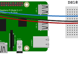
As an example to show you how to display readings from a sensor, this program prints temperature and humidity readings to the LCD using a DHT11 temperature and humidity sensor. To see how to set up the DHT11 on the Raspberry Pi, see our article How to Set Up the DHT11 Humidity Sensor on the Raspberry Pi.
The signal pin of the DHT11 is connected to physical pin 7 of the Raspberry Pi:
1 2 3 4 5 6 7 8 9 10 11 12 13 14 15 16 17 18 19 20 21 22 23 24 25 26 27 28 29 30 31 32 33 34 35 36 37 38 39 40 41 42 43 44 45 46 47 48 49 50 51 52 53 54 55 56 57 58 59 60 61 62 63 64 65 66 67 68 69 70 71 72 73 74 75 76 77 78 79 80 81 82 83 84 85 86 87 88 89 90 91 92 93 | #include <wiringPi.h> #include <lcd.h> #include <stdio.h> #include <stdlib.h> #include <stdint.h> //USE WIRINGPI PIN NUMBERS #define LCD_RS 25 //Register select pin #define LCD_E 24 //Enable Pin #define LCD_D4 23 //Data pin 4 #define LCD_D5 22 //Data pin 5 #define LCD_D6 21 //Data pin 6 #define LCD_D7 14 //Data pin 7 #define MAXTIMINGS 85 #define DHTPIN 7 int lcd; int dht11_dat[5] = {0, 0, 0, 0, 0}; void read_dht11_dat() { uint8_t laststate = HIGH; uint8_t counter = 0; uint8_t j = 0, i; float f; dht11_dat[0] = dht11_dat[1] = dht11_dat[2] = dht11_dat[3] = dht11_dat[4] = 0; pinMode(DHTPIN, OUTPUT); digitalWrite(DHTPIN, LOW); delay(18); digitalWrite(DHTPIN, HIGH); delayMicroseconds(40); pinMode(DHTPIN, INPUT); for (i = 0; i < MAXTIMINGS; i++) { counter = 0; while (digitalRead(DHTPIN) == laststate) { counter++; delayMicroseconds(1); if (counter == 255) { break; } } laststate = digitalRead(DHTPIN); if (counter == 255) break; if ((i >= 4) && (i % 2 == 0)) { dht11_dat[j / 8] <<= 1; if (counter > 16) dht11_dat[j / 8] |= 1; j++; } } if ((j >= 40) && (dht11_dat[4] == ((dht11_dat[0] + dht11_dat[1] + dht11_dat[2] + dht11_dat[3]) & 0xFF))) { f = dht11_dat[2] * 9. / 5. + 32; lcdPosition(lcd, 0, 0); lcdPrintf(lcd, "Humidity: %d.%d %%\n", dht11_dat[0], dht11_dat[1]); lcdPosition(lcd, 0, 1); //lcdPrintf(lcd, "Temp: %d.0 C", dht11_dat[2]); //Uncomment for Celsius lcdPrintf(lcd, "Temp: %.1f F", f); //Comment out for Celsius } } int main(void) { int lcd; wiringPiSetup(); lcd = lcdInit (2, 16, 4, LCD_RS, LCD_E, LCD_D4, LCD_D5, LCD_D6, LCD_D7, 0, 0, 0, 0); while (1) { read_dht11_dat(); delay(1000); } return(0); } | cs |
For temperature in Celsius, un-comment line 72, then comment out line 73.
Hopefully this helped you get your LCD up and running on your Raspberry Pi. The programs above are just basic examples, so try combining them to create interesting effects and animations.
If you have any problems or questions about installing the LCD or programming it, just leave a comment below. And don’t forget to subscribe to get an email when we publish new articles. Talk to you next time!
'개발자 > Raspberry Pi3' 카테고리의 다른 글
| Raspberry Pi Zero USB/Ethernet Gadget Tutorial (0) | 2018.06.21 |
|---|---|
| 온도 습도 센서 DHT11 에러. raspberry pi DHT11 센서 data not good skip error 해결 (0) | 2018.05.20 |
| DORJI DRF1276DM LoRa 모듈 timeout error 발생 해결 방법 (0) | 2018.02.02 |
| 868/915MHz LoRa Sx1276 UART interface Module DRF1276DM (0) | 2018.02.01 |
| 라즈베리 파이 LCD 사용 파이썬 RASPBERRY PI LCD AND PROGRAM IT WITH PYTHON (0) | 2017.10.24 |
| Raspberry pi DS18B20 Temperature Sensor 사용 데이터 읽기 Python 소스 (7) | 2017.10.24 |
| 미세먼지 측정 센서 Nova PM sensor SDS011 공기 품질 센서 사용법 (0) | 2017.10.18 |
| Sunfounder Car for Raspberry Pi 라즈베리 카 조립 시험 착수 (0) | 2017.10.17 |
취업, 창업의 막막함, 외주 관리, 제품 부재!
당신의 고민은 무엇입니까? 현실과 동떨어진 교육, 실패만 반복하는 외주 계약,
아이디어는 있지만 구현할 기술이 없는 막막함.
우리는 알고 있습니다. 문제의 원인은 '명확한 학습, 실전 경험과 신뢰할 수 있는 기술력의 부재'에서 시작됩니다.
이제 고민을 멈추고, 캐어랩을 만나세요!
코딩(펌웨어), 전자부품과 디지털 회로설계, PCB 설계 제작, 고객(시장/수출) 발굴과 마케팅 전략으로 당신을 지원합니다.
제품 설계의 고수는 성공이 만든 게 아니라 실패가 만듭니다. 아이디어를 양산 가능한 제품으로!
귀사의 제품을 만드세요. 교육과 개발 실적으로 신뢰할 수 있는 파트너를 확보하세요.
캐어랩