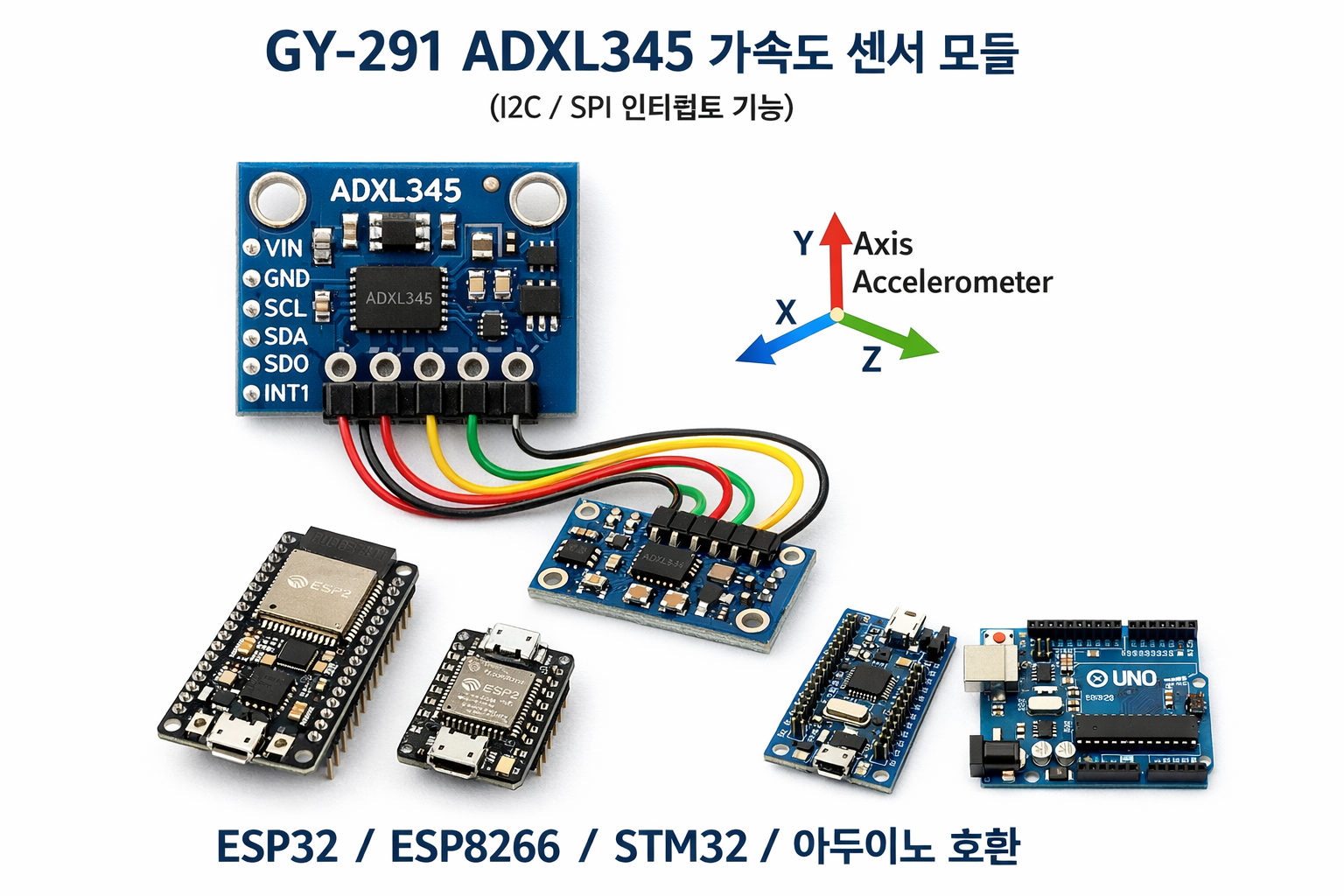
GY-291 ADXL345 i2c SPI 가속도 센서 (인터럽트 기능 포함) - ESP32, ESP8266, STM32 및 아두이노 호환
사랑을 전파하세요!
가속도계는 고유 가속도를 측정하는 도구입니다. 고유 가속도란 물체가 정지해 있는 순간의 기준계에서 측정한 가속도(속도의 변화율)를 말하며, 고정된 좌표계에서 측정한 가속도인 좌표 가속도와는 다릅니다.
목차는 다음과 같아요.
가속도계는 어떻게 작동하나요?
배선
아두이노 i2c 연결
아두이노 SPI 연결
ESP32 I2C 연결
ESP32 SPI 연결
ESP8266 I2C 연결
ESP8266 SPI 연결
라이브러리 Adafruit 인터럽트 없음
기본 스케치
인터럽트가 포함된 SparkFun 라이브러리
라이브러리 가져오기
가속도계를 이용한 경사각 추정
감사해요
ADXL345 는 소형, 초박형, 초저전력 3축 가속도계로, 최대 ±16g의 정밀도로 13비트 고해상도 측정이 가능합니다. 디지털 출력 데이터는 16비트 2의 보수 형식으로 저장되며, SPI(3선 또는 4선) 또는 I2C 디지털 인터페이스를 통해 접근할 수 있습니다.
GY-291 adxl345 i2c SPI 가속도 센서 아두이노 esp8266 esp32
ADXL345는 모바일 기기 애플리케이션에 매우 적합합니다. 기울기 감지 애플리케이션에서 정적 중력 가속도를 측정할 뿐만 아니라 움직임이나 충격으로 인한 동적 가속도도 측정합니다. 높은 해상도(3.9mg/LSB) 덕분에 1.0° 미만의 기울기 변화까지 측정할 수 있습니다.
이 모듈은 3.3V 및 5V 전원 공급을 지원하지만, 로직 레벨 변환기가 없으므로 장시간 통신을 위해서는 3.3V 연결이 필요합니다.
가속도계는 어떻게 작동하나요?
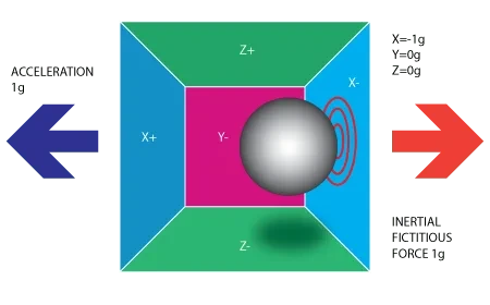
가속도계는 압전 효과의 원리를 이용합니다. 아래 그림처럼 직육면체 상자 안에 작은 공이 들어 있다고 상상해 보세요.

가속도계: 내부에 작은 공이 있는 직육면체 상자
이 상자의 벽은 압전 결정으로 만들어졌습니다. 상자를 기울이면 공은 기울어진 방향으로 움직이게 됩니다.
가속도계: 작은 공 모양의 가속도계가 내장된 직육면체
중력 때문에 공이 벽에 부딪히면서 미세한 압전 전류가 발생합니다. 직육면체에는 총 세 쌍의 마주보는 벽이 있으며, 각 쌍은 3차원 공간의 X, Y, Z축에 해당합니다.

가속도계: 중력 효과를 내는 작은 공이 들어 있는 직육면체 상자
압전벽에서 발생하는 전류에 따라 기울기의 방향과 크기를 결정할 수 있습니다.

가속도계: 중력을 발생시키는 작은 공이 들어 있는 직육면체 상자
각 가속도계는 무중력 전압 레벨을 가지고 있으며, 이는 가속도계 사양에서 확인할 수 있습니다. 또한 감도(일반적으로 mV/g로 표시됨)도 있습니다. 무중력 레벨 보정값을 감도로 나누면 최종 측정값이 나옵니다. 추의 편향은 추와 감지판 사이의 정전 용량 변화로 측정됩니다. 내부 회로는 이 미세한 정전 용량을 전압 신호로 변환하여 디지털화한 후 출력합니다.
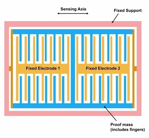
가속도계 구조의 움직임
이러한 특성 덕분에 가속도계는 자력계의 오차를 보정하는 데에도 사용할 수 있습니다.

가속도계를 이용한 항공기 오차 보정
자세한 내용은 비행 설명서를 참조하십시오 .
회로 연결
아두이노 i2c 연결
아두이노 UNO 의 경우 , 로직 전압이 5V인데 모듈은 3.3V(최대 3.6V)만 지원하므로 A4 및 A5 핀에 직접 연결하지 않는 것이 좋습니다. 연결하지 않아도 작동은 하지만, 모듈이 손상될 위험이 있습니다. 아래 회로도는 레벨 시프터를 함께 연결한 회로도입니다.

아두이노 UNO 및 ADXL345 I2C 로직 레벨 변환기
아두이노 SPI 연결
Spi는 연결이 더 어렵지만 속도가 더 빠릅니다.

아두이노 UNO 및 adxl345 SPI 로직 레벨 변환기
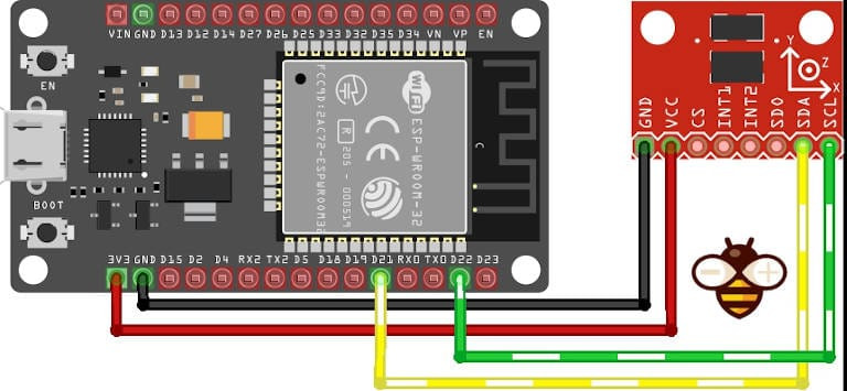
ESP32 I2C 연결
ESP8266과 ESP32는 3.3V 로직을 사용하므로 문제없이 작동합니다. ESP32는 표준 핀인 SDA와 SCL(GPIO21 및 GPIO22)을 통해 I2C 연결이 가능합니다.
esp32 doit 개발 키트 v1 adxl345 i2c
ESP32 SPI 연결
SS(GPIO05), MOSI(GPIO23), MISO(GPIO19), SCK(GPIO18) 핀은 각각 CS, SDA, SDO, SCL 핀에 해당하는 SPI 연결입니다.

ESP32 DOIT 개발 키트 v1 및 ADXL345 SPI 연결
ESP8266 I2C 연결
ESP8266에서는 SDA의 D4와 SCL의 D5가 사용됩니다.

esp8266 WeMos D1 및 adxl345 i2c
ESP8266 SPI 연결
esp8266은 CS에 SPI SS(D8), SDA에 D7(MOSI), SDO에 D6(MISO), SCL에 D5(SCK)를 갖추고 있습니다.

esp8266 WeMos D1 및 adxl345 SPI 연결
Adafruit 라이브러리 - 인터럽트 없음
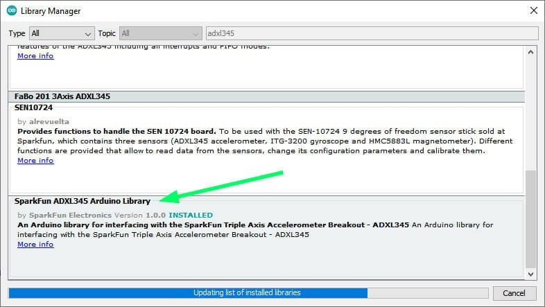
다양한 라이브러리가 있지만, 가장 간단한 것 중 하나는 Adafruit에서 제공하는 라이브러리입니다. GitHub 에서 관련 종속성인 `Adafruit Unified Sensor Driver` 와 함께 다운로드 하거나, Arduino IDE의 라이브러리 관리자에서 직접 사용할 수 있습니다.

아두이노 IDE 라이브러리 관리자 GY-291 adxl345
기본 스케치
다음은 가속도계에서 데이터를 가져오는 i2c 연결을 사용하는 간단한 스케치(라이브러리 예제)입니다.
#include <Wire.h>
#include <Adafruit_Sensor.h>
#include <Adafruit_ADXL345_U.h>

/* Assign a unique ID to this sensor at the same time */
Adafruit_ADXL345_Unified accel = Adafruit_ADXL345_Unified(12345);

void displaySensorDetails(void)
{
  sensor_t sensor;
  accel.getSensor(&sensor);
  Serial.println("------------------------------------");
  Serial.print  ("Sensor:       "); Serial.println(sensor.name);
  Serial.print  ("Driver Ver:   "); Serial.println(sensor.version);
  Serial.print  ("Unique ID:    "); Serial.println(sensor.sensor_id);
  Serial.print  ("Max Value:    "); Serial.print(sensor.max_value); Serial.println(" m/s^2");
  Serial.print  ("Min Value:    "); Serial.print(sensor.min_value); Serial.println(" m/s^2");
  Serial.print  ("Resolution:   "); Serial.print(sensor.resolution); Serial.println(" m/s^2");
  Serial.println("------------------------------------");
  Serial.println("");
  delay(500);
}

void displayDataRate(void)
{
  Serial.print  ("Data Rate:    ");

  switch(accel.getDataRate())
  {
    case ADXL345_DATARATE_3200_HZ:
      Serial.print  ("3200 ");
      break;
    case ADXL345_DATARATE_1600_HZ:
      Serial.print  ("1600 ");
      break;
    case ADXL345_DATARATE_800_HZ:
      Serial.print  ("800 ");
      break;
    case ADXL345_DATARATE_400_HZ:
      Serial.print  ("400 ");
      break;
    case ADXL345_DATARATE_200_HZ:
      Serial.print  ("200 ");
      break;
    case ADXL345_DATARATE_100_HZ:
      Serial.print  ("100 ");
      break;
    case ADXL345_DATARATE_50_HZ:
      Serial.print  ("50 ");
      break;
    case ADXL345_DATARATE_25_HZ:
      Serial.print  ("25 ");
      break;
    case ADXL345_DATARATE_12_5_HZ:
      Serial.print  ("12.5 ");
      break;
    case ADXL345_DATARATE_6_25HZ:
      Serial.print  ("6.25 ");
      break;
    case ADXL345_DATARATE_3_13_HZ:
      Serial.print  ("3.13 ");
      break;
    case ADXL345_DATARATE_1_56_HZ:
      Serial.print  ("1.56 ");
      break;
    case ADXL345_DATARATE_0_78_HZ:
      Serial.print  ("0.78 ");
      break;
    case ADXL345_DATARATE_0_39_HZ:
      Serial.print  ("0.39 ");
      break;
    case ADXL345_DATARATE_0_20_HZ:
      Serial.print  ("0.20 ");
      break;
    case ADXL345_DATARATE_0_10_HZ:
      Serial.print  ("0.10 ");
      break;
    default:
      Serial.print  ("???? ");
      break;
  }
  Serial.println(" Hz");
}

void displayRange(void)
{
  Serial.print  ("Range:         +/- ");

  switch(accel.getRange())
  {
    case ADXL345_RANGE_16_G:
      Serial.print  ("16 ");
      break;
    case ADXL345_RANGE_8_G:
      Serial.print  ("8 ");
      break;
    case ADXL345_RANGE_4_G:
      Serial.print  ("4 ");
      break;
    case ADXL345_RANGE_2_G:
      Serial.print  ("2 ");
      break;
    default:
      Serial.print  ("?? ");
      break;
  }
  Serial.println(" g");
}

void setup(void)
{
#ifndef ESP8266
  while (!Serial); // for Leonardo/Micro/Zero
#endif
  Serial.begin(9600);
  Serial.println("Accelerometer Test"); Serial.println("");

  /* Initialise the sensor */
  if(!accel.begin())
  {
    /* There was a problem detecting the ADXL345 ... check your connections */
    Serial.println("Ooops, no ADXL345 detected ... Check your wiring!");
    while(1);
  }

  /* Set the range to whatever is appropriate for your project */
  accel.setRange(ADXL345_RANGE_16_G);
  // accel.setRange(ADXL345_RANGE_8_G);
  // accel.setRange(ADXL345_RANGE_4_G);
  // accel.setRange(ADXL345_RANGE_2_G);

  /* Display some basic information on this sensor */
  displaySensorDetails();

  /* Display additional settings (outside the scope of sensor_t) */
  displayDataRate();
  displayRange();
  Serial.println("");
}

void loop(void)
{
  /* Get a new sensor event */
  sensors_event_t event;
  accel.getEvent(&event);

  /* Display the results (acceleration is measured in m/s^2) */
  Serial.print("X: "); Serial.print(event.acceleration.x); Serial.print("  ");
  Serial.print("Y: "); Serial.print(event.acceleration.y); Serial.print("  ");
  Serial.print("Z: "); Serial.print(event.acceleration.z); Serial.print("  ");Serial.println("m/s^2 ");
  delay(500);
}
SPI와 연결하려면 생성자를 변경해야 합니다.
//Adafruit_ADXL345_Unified accel = Adafruit_ADXL345_Unified(18, 19, 23, 5, 12345); ESP32 equivalent constructor
Adafruit_ADXL345_Unified accel = Adafruit_ADXL345_Unified(SCK, MISO, MOSI, SS, 12345);
다음은 스크립트의 직렬 출력 결과입니다.
------------------------------------
Sensor:       ADXL345
Driver Ver:   1
Unique ID:    12345
Max Value:    -156.91 m/s^2
Min Value:    156.91 m/s^2
Resolution:   0.04 m/s^2
------------------------------------

Data Rate:    100  Hz
Range:         +/- 16  g

X: -4.08  Y: -0.78  Z: 8.98  m/s^2
X: -4.04  Y: -0.78  Z: 8.94  m/s^2
X: -4.08  Y: -0.78  Z: 8.83  m/s^2
X: -4.08  Y: -0.75  Z: 8.90  m/s^2
X: -4.04  Y: -0.78  Z: 8.94  m/s^2
X: -4.08  Y: -0.78  Z: 8.98  m/s^2
X: -4.08  Y: -0.75  Z: 8.90  m/s^2
X: -4.00  Y: -0.78  Z: 8.90  m/s^2
X: -4.08  Y: -0.75  Z: 8.90  m/s^2
X: -4.08  Y: -0.75  Z: 8.94  m/s^2
X: -4.04  Y: -0.78  Z: 8.90  m/s^2
X: -4.04  Y: -0.78  Z: 8.94  m/s^2
X: -4.04  Y: -0.78  Z: 8.94  m/s^2
인터럽트가 포함된 SparkFun 라이브러리
이 장치는 스마트/생체 인식 로깅에 매우 유용한 다양한 인터럽트 모드를 제공합니다. 다음은 데이터시트에서 발췌한 정보입니다.
DATA_READY
비트는 새 데이터가 사용 가능할 때 설정되고 더 이상 사용할 수 없을 때 해제됩니다.
SINGLE_TAP
비트는 THRESH_TAP 레지스터(주소 0x1D)에 있는 값보다 큰 단일 가속 이벤트가 DUR 레지스터(주소 0x21)에 지정된 시간보다 짧은 시간 동안 발생할 때 설정됩니다.
DOUBLE_TAP
비트는 THRESH_TAP 레지스터(주소 0x1D)의 값보다 큰 두 개의 가속 이벤트가 DUR 레지스터(주소 0x21)에 지정된 시간보다 짧은 시간 동안 발생하고, 두 번째 탭이 latent 레지스터(주소 0x22)에 지정된 시간 이후에 시작되지만 window 레지스터(주소 0x23)에 지정된 시간 내에 시작될 때 설정됩니다.
활성
비트는 ACT_INACT_CTL 레지스터(주소 0x27)에 의해 설정된 THRESH_ACT 레지스터(주소 0x24)에 저장된 값보다 큰 가속도가 참여하는 축에서 발생할 때 설정됩니다.
비활성 상태
는 THRESH_INACT 레지스터(주소 0x25)에 저장된 값보다 작은 가속도가 ACT_INACT_CTL
레지스터(주소 0x27)에 의해 설정된 TIME_INACT 레지스터(주소 0x26)에 지정된 시간보다 모든 참여 축에서 더 오래 지속될 때 설정됩니다. TIME_INACT의 최대값은 255초입니다.
FREE_FALL
비트는 모든 축에서 THRESH_FF 레지스터(주소 0x28)에 저장된 값보다 작은 가속도가 TIME_FF 레지스터(주소 0x29)에 지정된 시간보다 오래 지속될 때(논리 AND 연산) 설정됩니다. FREE_FALL 인터럽트는 비활성 인터럽트와 다음과 같은 차이점이 있습니다. 모든 축이 항상 참여하고 논리 AND 연산이 수행되며, 타이머 주기가 훨씬 짧고(최대 1.28초), 동작 모드는 항상 DC 커플링 방식입니다.
워터마크
마크 비트는 FIFO의 샘플 수가 샘플 비트(FIFO_CTL 레지스터, 주소 0x38)에 저장된 값과 같아질 때 설정됩니다. FIFO를 읽을 때 워터마크 비트는 자동으로 해제되며, 내용은 샘플 비트에 저장된 값보다 작은 값으로 돌아갑니다.
라이브러리 가져오기
SparkFun 라이브러리 는 다소 복잡한 라이브러리이지만 i2c와 SPI를 지원하며 위에서 설명한 모든 인터럽트를 관리할 수 있게 해줍니다. GitHub 에서 다운로드 하거나 Arduino IDE의 라이브러리 관리자에서 직접 설치할 수 있습니다.
gy 291 adxl345 i2c SPI SparkFun 라이브러리 (인터럽트 포함) 아두이노 ESP32 및 ESP8266 지원
이 코드는 인터럽트 사용에 대한 완벽한 예제를 제공합니다.
/*  *********************************************
 *  SparkFun_ADXL345_Example
 *  Triple Axis Accelerometer Breakout - ADXL345
 *  Hook Up Guide Example
 *
 *  Utilizing Sparkfun's ADXL345 Library
 *  Bildr ADXL345 source file modified to support
 *  both I2C and SPI Communication
 *
 *  E.Robert @ SparkFun Electronics
 *  Created: Jul 13, 2016
 *  Updated: Sep 06, 2016
 *
 *  Development Environment Specifics:
 *  Arduino 1.6.11
 *
 *  Hardware Specifications:
 *  SparkFun ADXL345
 *  Arduino Uno
 *  *********************************************/

#include <SparkFun_ADXL345.h>         // SparkFun ADXL345 Library

/*********** COMMUNICATION SELECTION ***********/
/*    Comment Out The One You Are Not Using    */
ADXL345 adxl = ADXL345(10);           // USE FOR SPI COMMUNICATION, ADXL345(CS_PIN);
//ADXL345 adxl = ADXL345();             // USE FOR I2C COMMUNICATION

/****************** INTERRUPT ******************/
/*      Uncomment If Attaching Interrupt       */
//int interruptPin = 2;                 // Setup pin 2 to be the interrupt pin (for most Arduino Boards)

void ADXL_ISR();
/******************** SETUP ********************/
/*          Configure ADXL345 Settings         */
void setup(){

  Serial.begin(9600);                 // Start the serial terminal
  Serial.println("SparkFun ADXL345 Accelerometer Hook Up Guide Example");
  Serial.println();

  adxl.powerOn();                     // Power on the ADXL345

  adxl.setRangeSetting(16);           // Give the range settings
                                      // Accepted values are 2g, 4g, 8g or 16g
                                      // Higher Values = Wider Measurement Range
                                      // Lower Values = Greater Sensitivity

  adxl.setSpiBit(0);                  // Configure the device to be in 4 wire SPI mode when set to '0' or 3 wire SPI mode when set to 1
                                      // Default: Set to 1
                                      // SPI pins on the ATMega328: 11, 12 and 13 as reference in SPI Library

  adxl.setActivityXYZ(1, 0, 0);       // Set to activate movement detection in the axes "adxl.setActivityXYZ(X, Y, Z);" (1 == ON, 0 == OFF)
  adxl.setActivityThreshold(75);      // 62.5mg per increment   // Set activity   // Inactivity thresholds (0-255)

  adxl.setInactivityXYZ(1, 0, 0);     // Set to detect inactivity in all the axes "adxl.setInactivityXYZ(X, Y, Z);" (1 == ON, 0 == OFF)
  adxl.setInactivityThreshold(75);    // 62.5mg per increment   // Set inactivity // Inactivity thresholds (0-255)
  adxl.setTimeInactivity(10);         // How many seconds of no activity is inactive?

  adxl.setTapDetectionOnXYZ(0, 0, 1); // Detect taps in the directions turned ON "adxl.setTapDetectionOnX(X, Y, Z);" (1 == ON, 0 == OFF)

  // Set values for what is considered a TAP and what is a DOUBLE TAP (0-255)
  adxl.setTapThreshold(50);           // 62.5 mg per increment
  adxl.setTapDuration(15);            // 625 μs per increment
  adxl.setDoubleTapLatency(80);       // 1.25 ms per increment
  adxl.setDoubleTapWindow(200);       // 1.25 ms per increment

  // Set values for what is considered FREE FALL (0-255)
  adxl.setFreeFallThreshold(7);       // (5 - 9) recommended - 62.5mg per increment
  adxl.setFreeFallDuration(30);       // (20 - 70) recommended - 5ms per increment

  // Setting all interupts to take place on INT1 pin
  //adxl.setImportantInterruptMapping(1, 1, 1, 1, 1);     // Sets "adxl.setEveryInterruptMapping(single tap, double tap, free fall, activity, inactivity);"
                                                        // Accepts only 1 or 2 values for pins INT1 and INT2. This chooses the pin on the ADXL345 to use for Interrupts.
                                                        // This library may have a problem using INT2 pin. Default to INT1 pin.

  // Turn on Interrupts for each mode (1 == ON, 0 == OFF)
  adxl.InactivityINT(1);
  adxl.ActivityINT(1);
  adxl.FreeFallINT(1);
  adxl.doubleTapINT(1);
  adxl.singleTapINT(1);

//attachInterrupt(digitalPinToInterrupt(interruptPin), ADXL_ISR, RISING);   // Attach Interrupt

}

/****************** MAIN CODE ******************/
/*     Accelerometer Readings and Interrupt    */
void loop(){

  // Accelerometer Readings
  int x,y,z;
  adxl.readAccel(&x, &y, &z);         // Read the accelerometer values and store them in variables declared above x,y,z

  // Output Results to Serial
  /* UNCOMMENT TO VIEW X Y Z ACCELEROMETER VALUES */
  //Serial.print(x);
  //Serial.print(", ");
  //Serial.print(y);
  //Serial.print(", ");
  //Serial.println(z);

  ADXL_ISR();
  // You may also choose to avoid using interrupts and simply run the functions within ADXL_ISR();
  //  and place it within the loop instead.
  // This may come in handy when it doesn't matter when the action occurs.

}

/********************* ISR *********************/
/* Look for Interrupts and Triggered Action    */
void ADXL_ISR() {

  // getInterruptSource clears all triggered actions after returning value
  // Do not call again until you need to recheck for triggered actions
  byte interrupts = adxl.getInterruptSource();

  // Free Fall Detection
  if(adxl.triggered(interrupts, ADXL345_FREE_FALL)){
    Serial.println("*** FREE FALL ***");
    //add code here to do when free fall is sensed
  }

  // Inactivity
  if(adxl.triggered(interrupts, ADXL345_INACTIVITY)){
    Serial.println("*** INACTIVITY ***");
     //add code here to do when inactivity is sensed
  }

  // Activity
  if(adxl.triggered(interrupts, ADXL345_ACTIVITY)){
    Serial.println("*** ACTIVITY ***");
     //add code here to do when activity is sensed
  }

  // Double Tap Detection
  if(adxl.triggered(interrupts, ADXL345_DOUBLE_TAP)){
    Serial.println("*** DOUBLE TAP ***");
     //add code here to do when a 2X tap is sensed
  }

  // Tap Detection
  if(adxl.triggered(interrupts, ADXL345_SINGLE_TAP)){
    Serial.println("*** TAP ***");
     //add code here to do when a tap is sensed
  }
}
보시다시피, 이 라이브러리는 i2c와 SPI를 지원하며, 장치의 감도와 인터럽트 매개변수를 지정하기 위해 많은 데이터를 설정할 수 있습니다.

ESP32 DOIT 개발 키트 v1 ADXL345 I2C 인터럽트 배선
예제를 수정하여 ESP32 의 GPIO15 핀을 탭이나 더블 탭과 같은 동작에 대한 인터럽트로 사용하고, GPIO4 핀은 5초 동안의 비활성 상태를 감지하도록 했습니다.
/*  *********************************************
 *  ADXL345
 *  Triple Axis Accelerometer Breakout - ADXL345
 *  Utilizing Sparkfun's ADXL345 Library
 *  both I2C and SPI Communication with esp32
 *
 *
 *
 *  *********************************************/

#include <SparkFun_ADXL345.h>         // SparkFun ADXL345 Library

/*********** COMMUNICATION SELECTION ***********/
/*    Comment Out The One You Are Not Using    */
//ADXL345 adxl = ADXL345(10);           // USE FOR SPI COMMUNICATION, ADXL345(CS_PIN);
ADXL345 adxl = ADXL345();             // USE FOR I2C COMMUNICATION

/****************** INTERRUPT ******************/
/*      Uncomment If Attaching Interrupt       */
//int interruptPin = 2;                 // Setup pin 2 to be the interrupt pin (for most Arduino Boards)
volatile bool somethingAppend = false;
volatile bool nothingAppend = false;

void IRAM_ATTR pin1Interrupt() {
    somethingAppend = true;
}
void IRAM_ATTR pin2Interrupt() {
    nothingAppend = true;
}

/******************** SETUP ********************/
/*          Configure ADXL345 Settings         */
void setup(){

  Serial.begin(9600);                 // Start the serial terminal
  Serial.println("SparkFun ADXL345 Accelerometer Hook Up Guide Example");
  Serial.println();

  adxl.powerOn();                     // Power on the ADXL345

  adxl.setRangeSetting(16);           // Give the range settings
                                      // Accepted values are 2g, 4g, 8g or 16g
                                      // Higher Values = Wider Measurement Range
                                      // Lower Values = Greater Sensitivity

  adxl.setSpiBit(0);                  // Configure the device to be in 4 wire SPI mode when set to '0' or 3 wire SPI mode when set to 1
                                      // Default: Set to 1
                                      // SPI pins on the ATMega328: 11, 12 and 13 as reference in SPI Library

  adxl.setActivityXYZ(1, 0, 0);       // Set to activate movement detection in the axes "adxl.setActivityXYZ(X, Y, Z);" (1 == ON, 0 == OFF)
  adxl.setActivityThreshold(75);      // 62.5mg per increment   // Set activity   // Inactivity thresholds (0-255)

  adxl.setInactivityXYZ(1, 0, 0);     // Set to detect inactivity in all the axes "adxl.setInactivityXYZ(X, Y, Z);" (1 == ON, 0 == OFF)
  adxl.setInactivityThreshold(75);    // 62.5mg per increment   // Set inactivity // Inactivity thresholds (0-255)
  adxl.setTimeInactivity(5);         // How many seconds of no activity is inactive?

  adxl.setTapDetectionOnXYZ(0, 0, 1); // Detect taps in the directions turned ON "adxl.setTapDetectionOnX(X, Y, Z);" (1 == ON, 0 == OFF)

  // Set values for what is considered a TAP and what is a DOUBLE TAP (0-255)
  adxl.setTapThreshold(50);           // 62.5 mg per increment
  adxl.setTapDuration(15);            // 625 μs per increment
  adxl.setDoubleTapLatency(80);       // 1.25 ms per increment
  adxl.setDoubleTapWindow(200);       // 1.25 ms per increment

  // Set values for what is considered FREE FALL (0-255)
  adxl.setFreeFallThreshold(7);       // (5 - 9) recommended - 62.5mg per increment
  adxl.setFreeFallDuration(30);       // (20 - 70) recommended - 5ms per increment

  // Setting all interupts to take place on INT1 pin except inactivity on INT2
  adxl.setImportantInterruptMapping(1, 1, 1, 1, 2);     // Sets "adxl.setEveryInterruptMapping(single tap, double tap, free fall, activity, inactivity);"
                                                        // Accepts only 1 or 2 values for pins INT1 and INT2. This chooses the pin on the ADXL345 to use for Interrupts.
                                                        // This library may have a problem using INT2 pin. Default to INT1 pin.

  // Turn on Interrupts for each mode (1 == ON, 0 == OFF)
  adxl.InactivityINT(1);
  adxl.ActivityINT(1);
  adxl.FreeFallINT(1);
  adxl.doubleTapINT(1);
  adxl.singleTapINT(1);

//attachInterrupt(digitalPinToInterrupt(interruptPin), ADXL_ISR, RISING);   // Attach Interrupt
  pinMode(GPIO_NUM_4, INPUT);
  pinMode(GPIO_NUM_15, INPUT);

  attachInterrupt(digitalPinToInterrupt(GPIO_NUM_4), pin1Interrupt, RISING);
  attachInterrupt(digitalPinToInterrupt(GPIO_NUM_15), pin2Interrupt, RISING);

}

void ADXL_ISR();

#define INTERVAL 1000
unsigned long startTime = millis();

/****************** MAIN CODE ******************/
/*     Accelerometer Readings and Interrupt    */
void loop(){

  // Accelerometer Readings
  int x,y,z;
  adxl.readAccel(&x, &y, &z);         // Read the accelerometer values and store them in variables declared above x,y,z

  if (startTime + INTERVAL < millis()){
      // Output Results to Serial
      /* X Y Z ACCELEROMETER VALUES */
        Serial.print("values of X , Y , Z: ");
        Serial.print(x);
        Serial.print(" , ");
        Serial.print(y);
        Serial.print(" , ");
        Serial.println(z);

        double xyzG[3];
        double ax,ay,az;
        adxl.get_Gxyz(xyzG);
        ax = xyzG[0];
        ay = xyzG[1];
        az = xyzG[2];
        Serial.print("X=");
        Serial.print(ax);
        Serial.print(" g");
        Serial.print(" Y=");
        Serial.print(ay);
        Serial.print(" g");
        Serial.print(" Z=");
        Serial.print(az);
        Serial.println(" g");
        Serial.println("**********************");

          if (somethingAppend) {
            Serial.println(" ------> Something append!!");
            ADXL_ISR();
            somethingAppend = false;
          }
          if (nothingAppend) {
                Serial.println(" ------> Nothing append in the last 5 secs.!!");
                ADXL_ISR();
                nothingAppend = false;
            }

      startTime = millis();
  }
}

/********************* ISR *********************/
/* Look for Interrupts and Triggered Action    */
void ADXL_ISR() {

  // getInterruptSource clears all triggered actions after returning value
  // Do not call again until you need to recheck for triggered actions
  byte interrupts = adxl.getInterruptSource();

  // Free Fall Detection
  if(adxl.triggered(interrupts, ADXL345_FREE_FALL)){
    Serial.println("*** FREE FALL ***");
    //add code here to do when free fall is sensed
  }

  // Inactivity
  if(adxl.triggered(interrupts, ADXL345_INACTIVITY)){
    Serial.println("*** INACTIVITY ***");
     //add code here to do when inactivity is sensed
  }

  // Activity
//  if(adxl.triggered(interrupts, ADXL345_ACTIVITY)){
//    Serial.println("*** ACTIVITY ***");
//     //add code here to do when activity is sensed
//  }

  // Double Tap Detection
  if(adxl.triggered(interrupts, ADXL345_DOUBLE_TAP)){
    Serial.println("*** DOUBLE TAP ***");
     //add code here to do when a 2X tap is sensed
  }

  // Tap Detection
  if(adxl.triggered(interrupts, ADXL345_SINGLE_TAP)){
    Serial.println("*** TAP ***");
     //add code here to do when a tap is sensed
  }
}
다음은 테스트의 콘솔 출력입니다.
values of X , Y , Z: -3 , 16 , 27
X=-0.01 g Y=0.06 g Z=0.09 g
**********************
values of X , Y , Z: -3 , 16 , 27
X=-0.01 g Y=0.06 g Z=0.09 g
**********************
 ------> Nothing append in the last 5 secs.!!
*** INACTIVITY ***
values of X , Y , Z: -3 , 16 , 27
X=-0.01 g Y=0.06 g Z=0.09 g
**********************
values of X , Y , Z: -3 , 16 , 27
X=-0.01 g Y=0.06 g Z=0.09 g
**********************
values of X , Y , Z: -3 , 16 , 27
X=-0.01 g Y=0.06 g Z=0.09 g
**********************
values of X , Y , Z: 1 , -2 , 66
X=0.00 g Y=-0.01 g Z=0.23 g
**********************
values of X , Y , Z: -3 , 16 , 27
X=-0.01 g Y=0.06 g Z=0.09 g
**********************
 ------> Something append!!
*** DOUBLE TAP ***
*** TAP ***
values of X , Y , Z: -3 , 16 , 27
X=-0.01 g Y=0.06 g Z=0.09 g
**********************
values of X , Y , Z: -3 , 16 , 27
X=-0.01 g Y=0.06 g Z=0.09 g
**********************
values of X , Y , Z: -3 , 16 , 27
X=-0.01 g Y=0.06 g Z=0.09 g
**********************
values of X , Y , Z: -3 , 16 , 27
X=-0.01 g Y=0.06 g Z=0.09 g
**********************
values of X , Y , Z: -3 , 16 , 27
X=-0.01 g Y=0.06 g Z=0.09 g
**********************
 ------> Nothing append in the last 5 secs.!!
*** INACTIVITY ***
values of X , Y , Z: -3 , 16 , 27
X=-0.01 g Y=0.06 g Z=0.09 g
**********************
가속도계를 이용한 경사각 추정
위 방법을 사용하면 현재 기울기 각도를 정확하게 측정하여 로봇의 움직임을 제어하는 데 활용할 수 있습니다. 먼저 가속도계만을 사용하여 기울기 각도를 측정하는 방법을 살펴보겠습니다.
아래 그림과 같이 로봇이 정지해 있는 상태라고 가정해 보겠습니다(측면에서 본 모습이며, 가속도계는 로봇 본체 상단에 수직으로 설치되어 있습니다).

가속도계로부터 경사각을 계산하세요
경사각은 다음과 같이 계산할 수 있습니다.
cos(Axr) = Rx / R
cos(Ayr) = Ry / R
cos(Azr) = Rz / R
R = SQRT( Rx^2 + Ry^2 + Rz^2)
arccos() 함수(cos() 함수의 역함수)를 사용하여 각도를 구하세요.
Axr = arccos(Rx/R)
Ayr = arccos(Ry/R)
Azr = arccos(Rz/R)
따라서 0 위치에서 각도를 계산하는 함수는 다음과 같습니다.
float inclination=180.0*acos(az/sqrt(ax*ax+ay*ay+az*az))/M_PI;
초기 위치를 "재설정"하려면 초기 ax0, ay0 및 az0 값을 보정하는 이 함수를 사용할 수 있습니다.
float inclinationFromInitialValue = 180.0*acos( (ax0*ax + ay0*ay + az0*az)/sqrt( (ax*ax + ay*ay + az*az)*(ax0*ax0 + ay0*ay0 + az0*az0)))/M_PI;
결과 코드는 다음과 같습니다.
/*
 * GY-291 ADXL345 accelerometer test
 * Retrieve data and calculate angle of rotation with gravitational force
 * Angle from 0 of device and angle from initial position of device
 *
 *  by Mischianti Renzo <https://mischianti.org>
 *
 *  https://mischianti.org
 *
 */
#include <Wire.h>
#include <Adafruit_Sensor.h>
#include <Adafruit_ADXL345_U.h>

/* Assign a unique ID to this sensor at the same time */
//Adafruit_ADXL345_Unified accel = Adafruit_ADXL345_Unified(12345); // i2c connection
//Adafruit_ADXL345_Unified(uint8_t clock, uint8_t miso, uint8_t mosi, uint8_t cs, int32_t sensorID = -1);
//Adafruit_ADXL345_Unified accel = Adafruit_ADXL345_Unified(18, 19, 23, 5, 12345);
Adafruit_ADXL345_Unified accel = Adafruit_ADXL345_Unified(SCK, MISO, MOSI, SS, 12345); // SPI connection

void displaySensorDetails(void)
{
  sensor_t sensor;
  accel.getSensor(&sensor);
  Serial.println("------------------------------------");
  Serial.print  ("Sensor:       "); Serial.println(sensor.name);
  Serial.print  ("Driver Ver:   "); Serial.println(sensor.version);
  Serial.print  ("Unique ID:    "); Serial.println(sensor.sensor_id);
  Serial.print  ("Max Value:    "); Serial.print(sensor.max_value); Serial.println(" m/s^2");
  Serial.print  ("Min Value:    "); Serial.print(sensor.min_value); Serial.println(" m/s^2");
  Serial.print  ("Resolution:   "); Serial.print(sensor.resolution); Serial.println(" m/s^2");
  Serial.println("------------------------------------");
  Serial.println("");
  delay(500);
}

void displayDataRate(void)
{
  Serial.print  ("Data Rate:    ");

  switch(accel.getDataRate())
  {
    case ADXL345_DATARATE_3200_HZ:
      Serial.print  ("3200 ");
      break;
    case ADXL345_DATARATE_1600_HZ:
      Serial.print  ("1600 ");
      break;
    case ADXL345_DATARATE_800_HZ:
      Serial.print  ("800 ");
      break;
    case ADXL345_DATARATE_400_HZ:
      Serial.print  ("400 ");
      break;
    case ADXL345_DATARATE_200_HZ:
      Serial.print  ("200 ");
      break;
    case ADXL345_DATARATE_100_HZ:
      Serial.print  ("100 ");
      break;
    case ADXL345_DATARATE_50_HZ:
      Serial.print  ("50 ");
      break;
    case ADXL345_DATARATE_25_HZ:
      Serial.print  ("25 ");
      break;
    case ADXL345_DATARATE_12_5_HZ:
      Serial.print  ("12.5 ");
      break;
    case ADXL345_DATARATE_6_25HZ:
      Serial.print  ("6.25 ");
      break;
    case ADXL345_DATARATE_3_13_HZ:
      Serial.print  ("3.13 ");
      break;
    case ADXL345_DATARATE_1_56_HZ:
      Serial.print  ("1.56 ");
      break;
    case ADXL345_DATARATE_0_78_HZ:
      Serial.print  ("0.78 ");
      break;
    case ADXL345_DATARATE_0_39_HZ:
      Serial.print  ("0.39 ");
      break;
    case ADXL345_DATARATE_0_20_HZ:
      Serial.print  ("0.20 ");
      break;
    case ADXL345_DATARATE_0_10_HZ:
      Serial.print  ("0.10 ");
      break;
    default:
      Serial.print  ("???? ");
      break;
  }
  Serial.println(" Hz");
}

void displayRange(void)
{
  Serial.print  ("Range:         +/- ");

  switch(accel.getRange())
  {
    case ADXL345_RANGE_16_G:
      Serial.print  ("16 ");
      break;
    case ADXL345_RANGE_8_G:
      Serial.print  ("8 ");
      break;
    case ADXL345_RANGE_4_G:
      Serial.print  ("4 ");
      break;
    case ADXL345_RANGE_2_G:
      Serial.print  ("2 ");
      break;
    default:
      Serial.print  ("?? ");
      break;
  }
  Serial.println(" g");
}

void setup(void)
{
#ifndef ESP8266
  while (!Serial); // for Leonardo/Micro/Zero
#endif
  Serial.begin(9600);
  Serial.println("Accelerometer Test"); Serial.println("");

  /* Initialise the sensor */
  if(!accel.begin())
  {
    /* There was a problem detecting the ADXL345 ... check your connections */
    Serial.println("Ooops, no ADXL345 detected ... Check your wiring!");
    while(1);
  }

  /* Set the range to whatever is appropriate for your project */
  accel.setRange(ADXL345_RANGE_16_G);
  // accel.setRange(ADXL345_RANGE_8_G);
  // accel.setRange(ADXL345_RANGE_4_G);
  // accel.setRange(ADXL345_RANGE_2_G);

  /* Display some basic information on this sensor */
  displaySensorDetails();

  /* Display additional settings (outside the scope of sensor_t) */
  displayDataRate();
  displayRange();
  Serial.println("");
}

bool initialValue = true;

double az0 = 0;
double ax0 = 0;
double ay0 = 0;

void loop(void)
{
  /* Get a new sensor event */
  sensors_event_t event;
  accel.getEvent(&event);

  double az = event.acceleration.z;
  double ax = event.acceleration.x;
  double ay = event.acceleration.y;

  if (initialValue) {
      az0 = event.acceleration.z;
      ax0 = event.acceleration.x;
      ay0 = event.acceleration.y;

      initialValue = false;
  }

  float inclination=180.0*acos(az/sqrt(ax*ax+ay*ay+az*az))/M_PI;
  Serial.print("Inclination: from 0 -> ");
  Serial.print(inclination);

  float inclinationFromInitialValue = 180.0*acos( (ax0*ax + ay0*ay + az0*az)/sqrt( (ax*ax + ay*ay + az*az)*(ax0*ax0 + ay0*ay0 + az0*az0)))/M_PI;
  Serial.print("° - from initial value -> ");
  Serial.print(inclinationFromInitialValue);

  /* Display the results (acceleration is measured in m/s^2) */
  Serial.print("° - X: "); Serial.print(ax); Serial.print("  ");
  Serial.print("Y: "); Serial.print(ay); Serial.print("  ");
  Serial.print("Z: "); Serial.print(az); Serial.print("  ");Serial.println("m/s^2 ");

  delay(500);
}
직렬 출력은 다음과 같습니다.
Accelerometer Test

------------------------------------
Sensor:       ADXL345
Driver Ver:   1
Unique ID:    12345
Max Value:    -156.91 m/s^2
Min Value:    156.91 m/s^2
Resolution:   0.04 m/s^2
------------------------------------

Data Rate:    100  Hz
Range:         +/- 16  g

Inclination: from 0 -> 25.15° - from initial value -> 0.00° - X: -4.16  Y: -0.43  Z: 8.90  m/s^2
Inclination: from 0 -> 24.46° - from initial value -> 0.76° - X: -4.04  Y: -0.47  Z: 8.94  m/s^2
Inclination: from 0 -> 24.76° - from initial value -> 0.48° - X: -4.08  Y: -0.47  Z: 8.90  m/s^2
Inclination: from 0 -> 24.39° - from initial value -> 0.77° - X: -4.00  Y: -0.39  Z: 8.87  m/s^2
Inclination: from 0 -> 24.78° - from initial value -> 0.62° - X: -4.08  Y: -0.51  Z: 8.90  m/s^2
Inclination: from 0 -> 24.88° - from initial value -> 0.57° - X: -4.08  Y: -0.51  Z: 8.87  m/s^2
Inclination: from 0 -> 20.58° - from initial value -> 5.11° - X: -3.26  Y: 0.00  Z: 8.67  m/s^2
Inclination: from 0 -> 52.23° - from initial value -> 28.91° - X: -7.10  Y: 1.41  Z: 5.61  m/s^2
Inclination: from 0 -> 70.47° - from initial value -> 49.04° - X: -8.90  Y: 3.65  Z: 3.41  m/s^2
Inclination: from 0 -> 77.11° - from initial value -> 56.65° - X: -8.71  Y: 4.43  Z: 2.24  m/s^2
Inclination: from 0 -> 87.06° - from initial value -> 68.87° - X: -8.00  Y: 5.88  Z: 0.51  m/s^2
Inclination: from 0 -> 94.68° - from initial value -> 76.98° - X: -7.81  Y: 6.35  Z: -0.82  m/s^2
Inclination: from 0 -> 102.48° - from initial value -> 84.43° - X: -7.69  Y: 6.28  Z: -2.20  m/s^2
Inclination: from 0 -> 102.26° - from initial value -> 84.13° - X: -7.73  Y: 6.24  Z: -2.16  m/s^2
Inclination: from 0 -> 103.35° - from initial value -> 85.46° - X: -7.61  Y: 6.35  Z: -2.35  m/s^2
Inclination: from 0 -> 105.40° - from initial value -> 87.56° - X: -7.37  Y: 6.28  Z: -2.67  m/s^2
Inclination: from 0 -> 97.58° - from initial value -> 78.79° - X: -8.12  Y: 5.88  Z: -1.33  m/s^2
Inclination: from 0 -> 106.23° - from initial value -> 84.68° - X: -8.71  Y: 4.28  Z: -2.82  m/s^2
Inclination: from 0 -> 106.06° - from initial value -> 83.50° - X: -9.02  Y: 3.49  Z: -2.79  m/s^2
Inclination: from 0 -> 112.29° - from initial value -> 89.72° - X: -8.36  Y: 3.33  Z: -3.69  m/s^2
Inclination: from 0 -> 52.47° - from initial value -> 28.98° - X: -9.14  Y: 1.69  Z: 7.14  m/s^2
Inclination: from 0 -> 30.41° - from initial value -> 8.93° - X: -5.06  Y: 0.86  Z: 8.75  m/s^2
Inclination: from 0 -> 24.27° - from initial value -> 17.12° - X: -2.94  Y: 2.12  Z: 8.04  m/s^2
감사해요.
이 튜토리얼의 작성자에게 감사합니다. 원문 기사를 다음 링크를 따라가세요.
'ESP32' 카테고리의 다른 글
| ESP32 보드에서 구동되는 초경량 오픈소스 'zclaw' 공개 (1) | 2026.02.25 |
|---|---|
| 연결이 끊긴 ESP32를 Wi-Fi 네트워크에 다시 연결하는 방법 (0) | 2026.02.24 |
| ESP32 MPU-6050 가속도계 및 자이로스코프 웹 서버 (0) | 2026.02.17 |
| ESP32 ADXL345 Accelerometer Interfacing (0) | 2026.02.17 |
| ESP32 MPU-6050 웹 서버 3D 객체 표현 (0) | 2026.02.14 |
| ESP32-P4 vs. C3: 어떤 Elecrow HMI 디스플레이가 당신에게 더 적합할까요? (0) | 2026.02.09 |
| ESP32 웹 업데이터: 브라우저를 통해 코드 업데이트(OTA) (0) | 2026.02.03 |
| ESP32와 PIR 모션 센서 사용, 인터럽트 및 타이머 (0) | 2026.01.30 |
취업, 창업의 막막함, 외주 관리, 제품 부재!
당신의 고민은 무엇입니까? 현실과 동떨어진 교육, 실패만 반복하는 외주 계약,
아이디어는 있지만 구현할 기술이 없는 막막함.
우리는 알고 있습니다. 문제의 원인은 '명확한 학습, 실전 경험과 신뢰할 수 있는 기술력의 부재'에서 시작됩니다.
이제 고민을 멈추고, 캐어랩을 만나세요!
코딩(펌웨어), 전자부품과 디지털 회로설계, PCB 설계 제작, 고객(시장/수출) 발굴과 마케팅 전략으로 당신을 지원합니다.
제품 설계의 고수는 성공이 만든 게 아니라 실패가 만듭니다. 아이디어를 양산 가능한 제품으로!
귀사의 제품을 만드세요. 교육과 개발 실적으로 신뢰할 수 있는 파트너를 확보하세요.
캐어랩


